Hydraulic piece table position fast changing device

A technology for hydraulic parts and positioning columns, which is applied in the field of quick-change devices for hydraulic parts, can solve problems such as waste of resources, high-pressure oil injection, injury to test personnel, etc., and achieve the effects of strong practicability, prevention of oil leakage, and reasonable structure.

Active Publication Date: 2019-11-15
YANTAI ZHONGYU AEROHYDRAULIC
View PDF0 Cites 4 Cited by
  • Summary
  • Abstract
  • Description
  • Claims
  • Application Information

AI Technical Summary

Problems solved by technology

[0004] Based on the background technology, there is an unstable connection between the existing hydraulic parts and the connecting valve. When the pressure measuring oil pipe is disassembled, it is easy to cause high-pressure oil injection, which will cause injury to the test personnel or pollute the test environment, and also waste resources. problem, the present invention proposes a quick-change device for hydraulic parts

Method used


Image

  • Hydraulic piece table position fast changing device
  • Hydraulic piece table position fast changing device
  • Hydraulic piece table position fast changing device

Examples


Embodiment 1

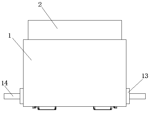
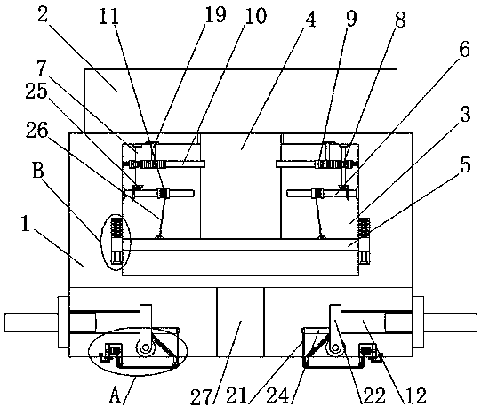
[0024] refer to Figure 1-5 In this embodiment, a quick-change device for hydraulic parts is proposed, including a connecting valve 1 and a hydraulic part main body 2. A cavity 3 is provided on the connecting valve 1, and a positioning column 4 is fixedly connected to the bottom of the hydraulic part main body 2. The bottom of the positioning column 4 runs through the top of the connecting valve 1 and extends into the cavity 3. A sliding plate 5 is slidably connected in the cavity 3. The bottom of the positioning column 4 is in contact with the top of the sliding plate 5. Both sides of the cavity 3 Two first rotating rods 6 are rotatably connected on the inner wall, and a second rotating rod 7 is connected to the first rotating rod 6. The fixed sleeve on the second rotating rod 7 is provided with a gear 8, and two tooth racks 9 are slidably connected to each other on the top inner wall of the cavity 3, the gear 8 is meshed with the tooth rack 9, and the sides of the two tooth ...

Embodiment 2

[0033] refer to Figure 1-5 In this embodiment, a quick-change device for hydraulic parts is proposed, which includes a connecting valve 1 and a main body 2 of the hydraulic part. The bottom of the column 4 runs through the top of the connecting valve 1 and extends into the cavity 3. A sliding plate 5 is slidably connected in the cavity 3. The bottom of the positioning column 4 is in contact with the top of the sliding plate 5. The inner walls on both sides of the cavity 3 There are two first rotating rods 6 connected to each other in rotation, and a second rotating rod 7 is connected to the first rotating rod 6. The tops of the two second rotating rods 7 are connected to the top inner wall of the cavity 3 in rotation. The rotating rod 7 is fixedly sleeved with a gear 8, and the top inner wall of the cavity 3 is slidably connected with two racks 9, the gear 8 is meshed with the rack 9, and the sides of the two racks 9 are welded to each other. Bayonet 10, both sides of positi...


PUM


Abstract

The invention belongs to the field of detecting equipment and particularly relates to a hydraulic piece table position fast changing device directing at the problems that an existing hydraulic piece and a connection valve are instable in connection, when a pressure measuring oil pipe is disassembled, high-pressure oil injection can be caused very easily, injuries are caused to test personnel or the test environment is polluted, and meanwhile resource waste is also caused. Now the following scheme is put forwards, the hydraulic piece table position fast changing device comprises a connection valve and a hydraulic piece body; the connection valve is provided with a cavity; and a positioning column is fixedly connected to the bottom of the hydraulic piece body. The hydraulic piece table position fast changing device is reasonable in structure, and due to fast fixing on the hydraulic piece body, the oil leaking problem generated between the connection valve and the hydraulic piece body canbe effectively solved; a first rotating shaft is rotated so that two sealing plates can be used for sealing a through pipe, it can be effectively prevented that when a pressure measuring oil pipe isdisassembled, high pressure oil injection is caused, the test personnel are injured or the test environment is polluted, meanwhile resources are saved, and high practicability is achieved.

Description

technical field [0001] The invention relates to the technical field of detection equipment, in particular to a quick-change device for hydraulic parts. Background technique [0002] Hydraulic components are all components used in hydraulic systems such as hydraulic pumps, hydraulic motors, hydraulic cylinders, hydraulic valves, and boosters. [0003] At present, some hydraulic parts test benches use threaded joints, quick-change joints and oil pipes to connect with the test bench, but the existing hydraulic parts and connecting valves are not connected stably, because the pressure during the hydraulic parts test is between 35-50bar During the disassembly of the connecting oil pipe in the valve body of the existing hydraulic parts, it is easy to cause high-pressure oil injection, which will cause injury to the test personnel or pollute the test environment, and will also waste resources. Therefore, we propose a hydraulic part platform A quick change device is used to solve t...

Claims


Application Information

Patent Timeline
Patent Type & Authority Applications(China)
IPC IPC(8): F15B19/00F15B21/00
CPCF15B19/00F15B21/00
Inventor 倪宇佩李祥至
Owner YANTAI ZHONGYU AEROHYDRAULIC
Why Eureka
Try Eureka