Full-automatic setting machine

A fully automatic stacking machine and driving wheel technology, applied in the field of stacking machines, can solve the problems of low installed power, high maintenance cost, easy oil leakage of hydraulic devices, etc., achieve stable operation, low maintenance cost, and reduce loosening of connecting screws Effect

Inactive Publication Date: 2016-02-24
洛阳润信机械制造有限公司
View PDF7 Cites 8 Cited by
  • Summary
  • Abstract
  • Description
  • Claims
  • Application Information

AI Technical Summary

Problems solved by technology

[0002] In the past, brick-making enterprises used manual handling and stacking of the formed bricks on the kiln car. Due to the high brick output per unit time of the brick production line and the freshly produced bricks were wet and heavy, they needed to be transported and stacked. The labor intensity is high, and the quality of adobe stacking is inconsistent. With the progress of society and technology, various high-tech enterprises are gradually improving the working environment of employees and increasing the technological content of the company. High requirements are gradually shifting from heavy physical labor to light physical or mental labor, and the labor cost of enterprises is also gradually increasing. High strength, low production efficiency, and inconsistent quality of adobe stacking are serious challenges. The shortage of labor force faced by manual brick-making enterprises is becoming increasingly prominent. How to ensure normal production without increasing production costs has become a must for every new brick-making enterprise. Considering the problem, now brick-making enterprises need to use automation equipment to replace labor work, and fully automatic billet stacking machine came into being
[0003] The working process of the automatic adobe stacking machine is that after the adobes produced by the brick making machine are grouped by the belt conveyor, the gripper of the automatic adobe coder descends to grab the adobes, and after being raised, it moves horizontally to the top of the kiln car. The gripper completes the splitting action, the gripper of the automatic stacking machine drops to the height of the stacking blanks for stacking and then rises, the gripper rotates and moves horizontally back to the top of the belt conveyor, the stacking machine stacks one layer, rotates one layer, and forms Crossing, through the above action cycle, the entire stacking process of the kiln car can be completed. In a working cycle of the automatic stacking machine, it needs to move up and down once, horizontally back and forth once, and the gripper rotates back and forth once, and the gripper is completed. The billet splitting action requires fast and stable horizontal moving speed, lifting speed, billet splitting speed, fast rotation speed and high motion accuracy during the working process of the automatic billet stacking machine. At the same time, the installed power of the whole machine should be small and the cost should be low. The lifting device of the fully automatic billet stacking machine uses a hydraulic device and a chain transmission device to directly drive the lifting gripper. The speed basically meets the palletizing requirements, but the power of the transmission part of the lifting device is large, the operation vibration is large, and the operating cost is high. In addition, the hydraulic device is prone to oil leakage. , the control valve is easy to block (card valve), the hydraulic oil needs to be replaced regularly, the maintenance cost is high, the power of the hydraulic device and the chain transmission device are large, and the volume and weight are also large. The speed of the horizontal moving device of the existing automatic stacking machine basically meets the palletizing However, due to the unreasonable structure of the horizontal moving device, the jitter and vibration during the movement are relatively serious. The existing automatic stacking machine rotating device adopts a hydraulic device or a servo push rod. The speed and motion accuracy basically meet the palletizing requirements. The servo push rod rotates The cost of the device is high, the hydraulic device is easy to leak oil, the control valve is easy to block (card valve), the hydraulic oil needs to be replaced regularly, and the maintenance cost is high

Method used


Image

  • Full-automatic setting machine

Examples


Embodiment Construction

[0019] Implementation column 1

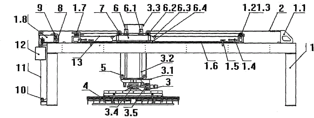
[0020] As shown in the figure, the rear end of the crossbeam of the underframe (1) is provided with a rear support (1.1), the front end of the crossbeam of the underframe (1) is provided with a front support (1.8), and the track (1.6) is arranged on the crossbeam of the underframe (1). On the top, the two ends of the track (1.6) are provided with a limit device (1.5); the driving device (1.4) is provided behind the limit device (1.5), and a slider (6.4) is provided under the walking trolley (6). (6) The slider (6.4) set at the bottom is set on the track (1.6), the guide sleeve (6.1) is set on the trolley (6), the guide column (3.2) is set in the guide sleeve (6.1), and the lifting frame (3 ) is arranged below the guide post (3.2), and the upper end of the guide post (3.2) is provided with a (3.3) lower sensor; the lift frame (3) is arranged below the guide post (3.2), and the lift frame (3) ) is provided with a central bearing (3.4), and the p...


PUM


Abstract

The invention provides a full-automatic setting machine. A frequency conversion gear motor (8) is arranged on a front support (1.8), and a transmission chain wheel (9) is arranged on the frequency conversion gear motor (8). One end of a transmission chain (11) is connected to a balance weight (12), and the other end of the transmission chain (11) penetrates a middle chain wheel (10) arranged below a rack (1) and is connected to the position below the balance weight (12). One end of a steel wire rope (2) is connected with a rear support (1.1), and the other end of the steel wire rope (2) sequentially penetrates a synchronous belt riding wheel (6.2), a movable pulley (5) and a fixed pulley (7) to be connected with the balance weight (12). An upper wheel line of a synchronous belt driving wheel and an upper wheel line of a synchronous belt driven wheel are located in the same plane, stable operating is achieved, and no shaking or vibration is generated. The brick falling frequency is reduced, and the problems that a connecting screw is loosened and a structure piece cracks due to vibration are reduced. Meanwhile, pure mechanical transmission is adopted, so that the faults of oil leakage, control valve blocking (valve clamping) and the like are completely eradicated, hydraulic oil does not need to be replaced, and maintenance cost is low.

Description

technical field [0001] The invention relates to a blank stacking machine in wall material automation equipment, in particular to a fully automatic blank stacking machine. Background technique [0002] In the past, brick-making enterprises used manual handling and stacking of the formed bricks on the kiln car. Due to the high brick output per unit time of the brick production line and the freshly produced bricks were wet and heavy, they needed to be transported and stacked. The labor intensity is high, and the quality of adobe stacking is inconsistent. With the progress of society and technology, various high-tech enterprises are gradually improving the working environment of employees and increasing the technological content of the company. High requirements are gradually shifting from heavy physical labor to light physical or mental labor, and the labor cost of enterprises is also gradually increasing. High strength, low production efficiency, and inconsistent quality of a...

Claims


Application Information

Patent Timeline
Patent Type & Authority Applications(China)
IPC IPC(8): B65G61/00
CPCB65G61/00
Inventor 李延山
Owner 洛阳润信机械制造有限公司
Why Eureka
Try Eureka