Structure of stapling device

a stapling device and metal casing technology, applied in the direction of nailing tools, packaging, paper/cardboard containers, etc., can solve the problems of increasing the number of components, increasing the cost, and complicated structure, so as to effectively absorb the impact force and reduce the loosening caused by vibration. , the effect of reducing the risk of damag

Inactive Publication Date: 2015-02-12
JANN YEI IND
View PDF14 Cites 10 Cited by
  • Summary
  • Abstract
  • Description
  • Claims
  • Application Information

AI Technical Summary

Benefits of technology

[0009]As such, with the above-described technical solution so provided, the design of forming front-end tabs on two casing members of the stapling device according to the present invention to define, collectively with a pad seat, a striker plate channel for slidably receiving therein a staple striker plate and clamping and retaining a spring plate between two casing members to provide the staple striker plate with a striking pre-loading force with the spring plate enables the present invention to form an external device casing by simply combining the two casing members without inclusion of a staple striker seat that is conventionally used to generate a striking pre-loading force for a staple striker plate, whereby the present invention can greatly simplifies the structure, making it easy for manufacturing and assembling and effectively lowering down the cost.
[0010]Another object of the present invention is to provide a structure of a stapling device of high safety, which can effectively absorbs the impact force induced by striking of staples in order to alleviate loosening caused by vibration and effectively extend the lifespan.
[0011]The present invention adopts the following technical solution to achieve the above object and desired performance, wherein the pad seat has a top to which a flexible pad is mounted to be depressed by the spring plate and the flexible pad is made of a rubber material to provide a cushioning effect.
[0012]As such, when the spring plate is moved downward for position returning, the underside of the front end thereof hits the flexible pad mounted to the top of the pad seat and a cushioning effect is induced to alleviate vibration caused by staple striking so as to prevent components from getting loosened and damaged due to vibration.
[0013]In summary, the present invention provides significant improvements in various aspects regarding simplification of structure, reduction of cost, and extension of lifespan.

Problems solved by technology

This increases the components and the overall size and also raises the cost.
In other words, the design of the conventional metal-casing stapling device must take the formation of the striker plate channel and the staple-striking pre-loading into consideration and thus, the number of components is increased and the structure is complicated.
This in turn makes the assembling difficult and raises the manufacturing cost.
Further, the conventional device has a poor effect of absorbing striking force during the staple striking operations so that, being acted upon by long term successive striking, the components may get easily loosened due to vibrations.
This affects the performance of staple striking and also leads to damage and shortening of lifespan.

Method used


Image

  • Structure of stapling device
  • Structure of stapling device
  • Structure of stapling device

Examples


Embodiment Construction

[0027]The following descriptions are exemplary embodiments only, and are not intended to limit the scope, applicability or configuration of the invention in any way. Rather, the following description provides a convenient illustration for implementing exemplary embodiments of the invention. Various changes to the described embodiments may be made in the function and arrangement of the elements described without departing from the scope of the invention as set forth in the appended claims

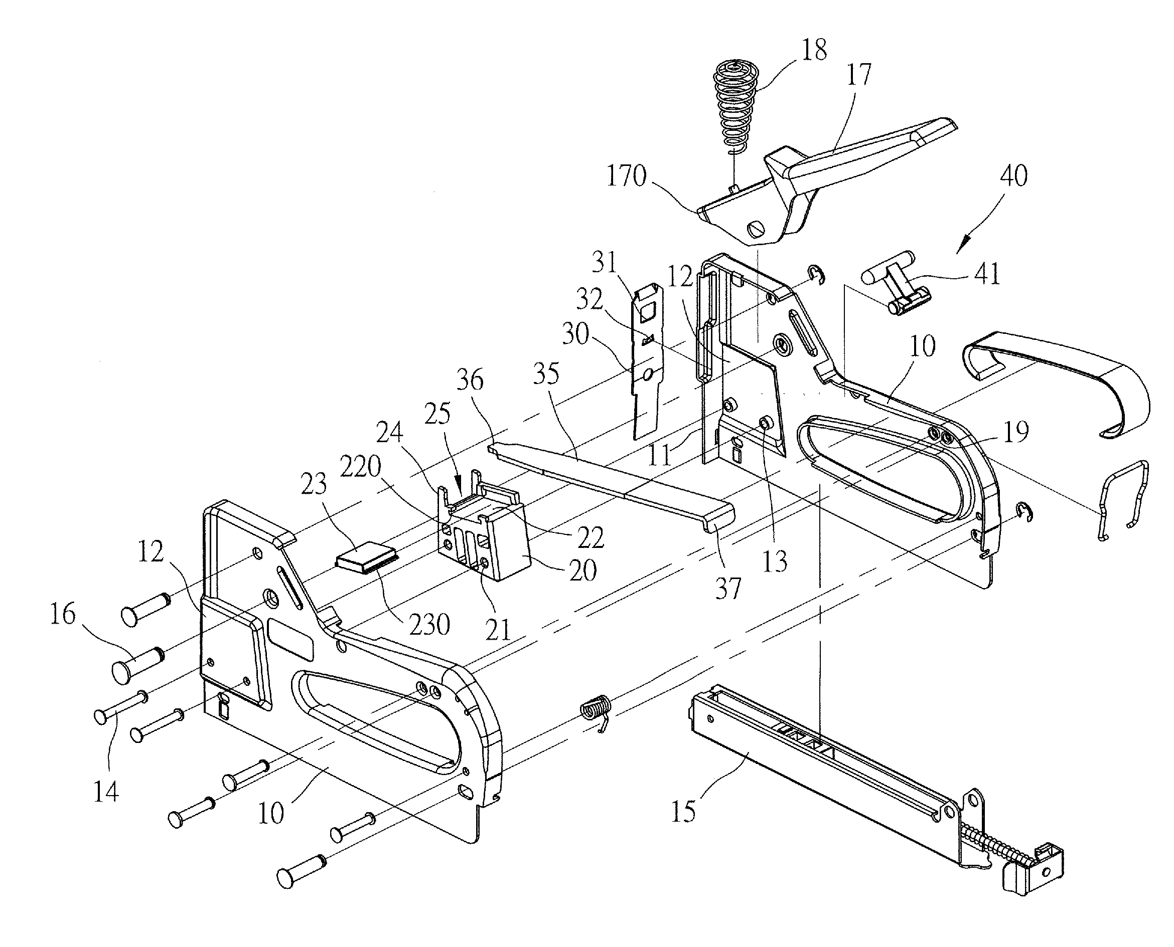
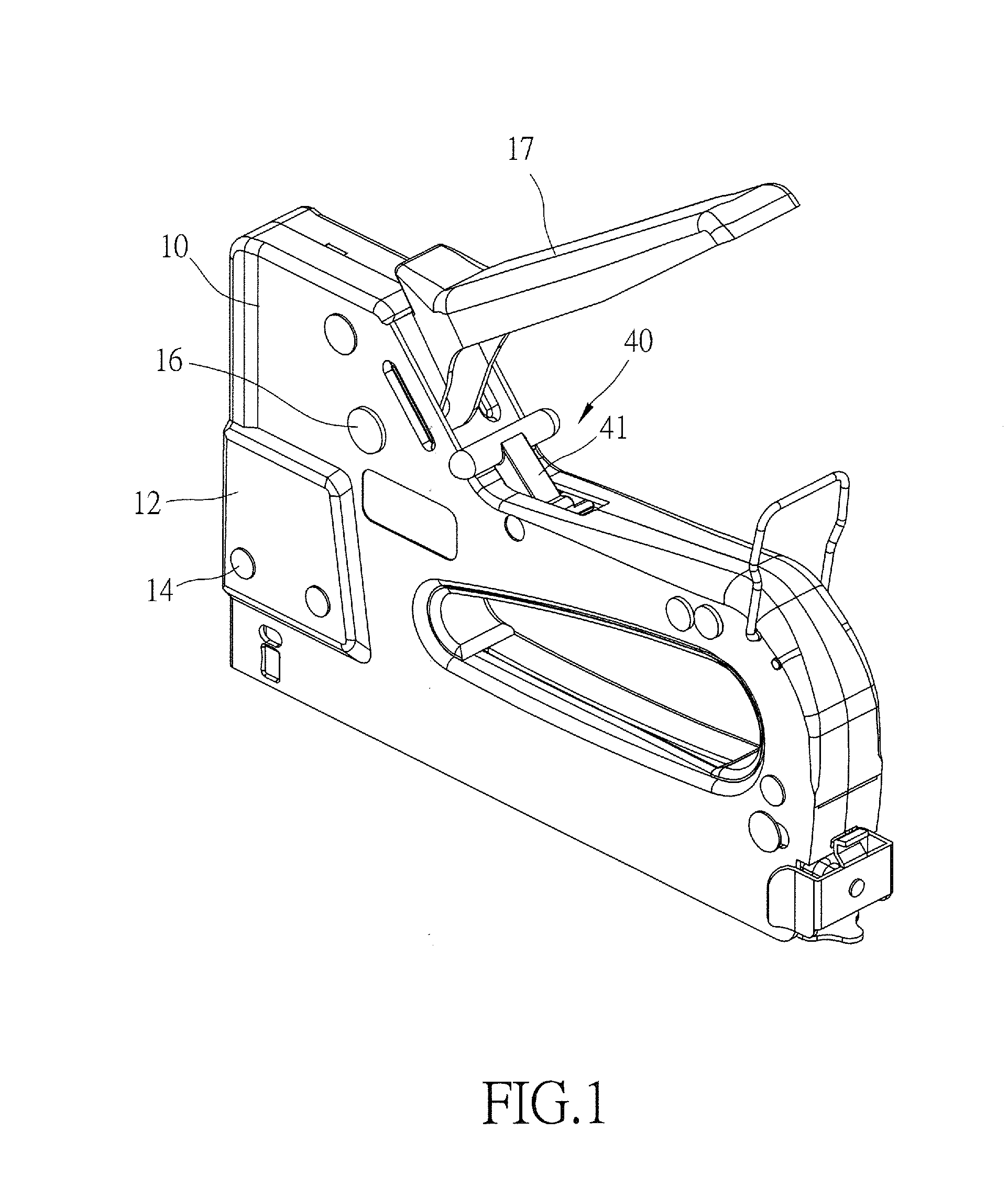
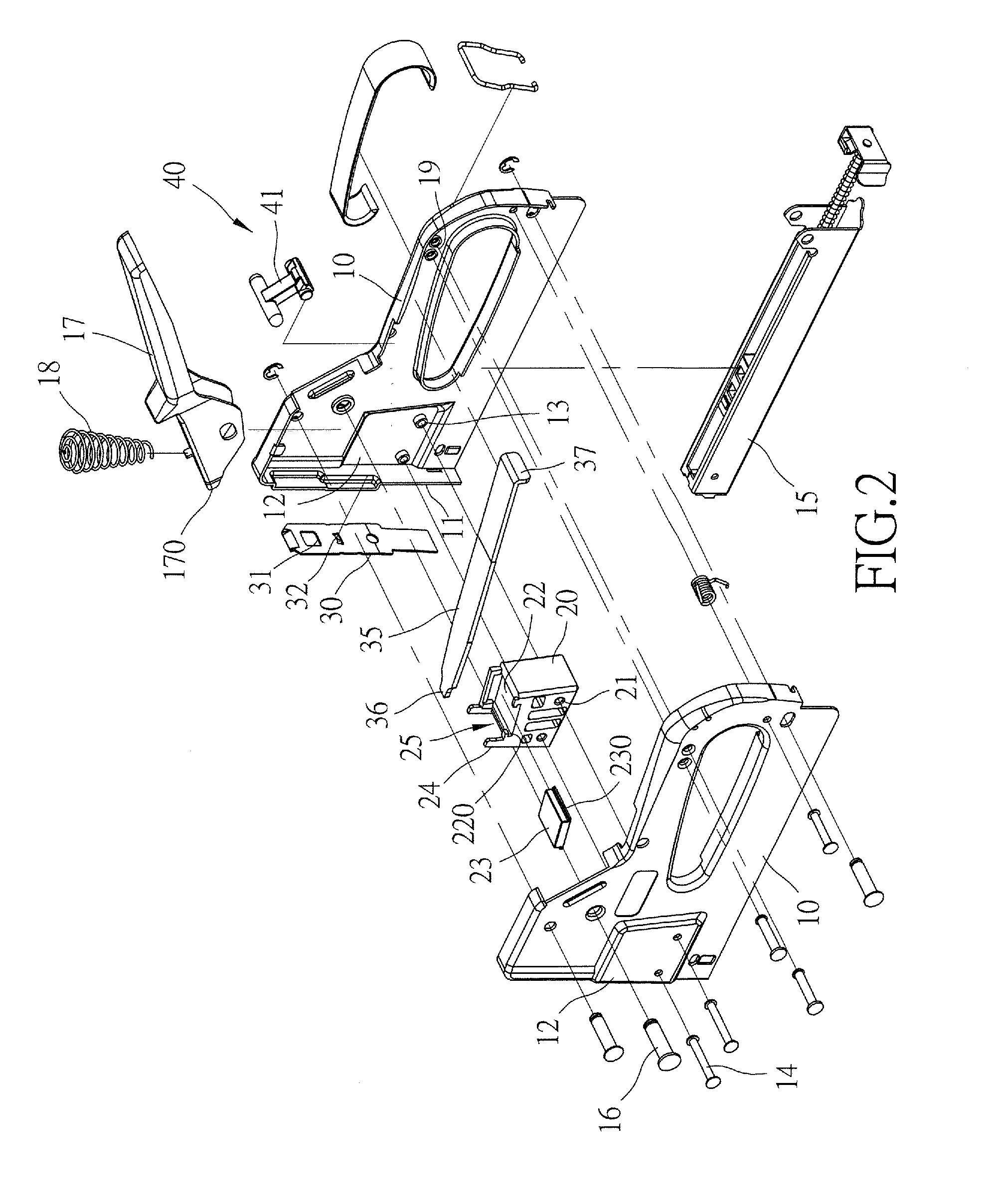
[0028]The present invention provides a structure of a stapling device, which, as shown in FIGS. 1 and 2, comprises two casing members 10 that are mateable and combinable with each other. The two casing members 10 are rotatably coupled, by means of a pivot pin 16, to a press-down handle 17 that is selectively depressible downward. The two casing members 10 comprises therein a striker plate channel 25 that is formed in a pad seat 20 arranged at the bottom of the front end thereof. The striker plate cha...


PUM


Abstract

A stapling device includes two casing members, a pad seat, and a striker plate. The casing members, which can be combined together, have front ends respectively forming front-end plates abutting each other. The two casing members are rotatably coupled to a press-down handle that is selectively pressed down. The pad seat is set at the front end of the interior of the two combined casing members. The pad seat has a front end face, which define, collectively with the inside surfaces of the front-end plates of the two casing members, a striker plate channel. The striker plate is slidably received in the striker plate channel. The striker plate is selectively pulled by the press-down handle to move upward. The two casing members clamp and retain therebetween a spring plate for providing a striking pre-loading force to the striker plate.

Description

(a) TECHNICAL FIELD OF THE INVENTION[0001]The present invention relates to the technical field of metal-casing stapling devices, and more particularly to a structure of a metal-casing stapling device, which reduces the number of components, lowers down assembling cost, provide a cushioning effect, and extends the lifespan of the stapling device.(b) DESCRIPTION OF THE PRIOR ART[0002]Stapling devices are generally divided into two categories, which are metal-casing stapling devices and plastic-casing stapling device. A known metal-casing stapling device comprises a casing that is composed of two side covers 51 that mates and are connectable to each other and a front lid 52. In order to form a striker plate channel 54 along which a staple striker plate 53 is slidable, the front lid 52 is additionally mounted to a front end of the combined side covers 51. Further, due to the fact that the metal side covers 51 cannot be directly formed with a spring retention slot, a compressible powerfu...

Claims


Application Information

Patent Timeline
Patent Type & Authority Applications(United States)
IPC IPC(8): B25C5/06
CPCB25C5/06B25C5/11
Inventor CHEN, TON-YI
Owner JANN YEI IND
Why Eureka
Try Eureka