Tripod type constant velocity universal joint

a constant velocity, universal joint technology, applied in the direction of yielding couplings, couplings, mechanical devices, etc., can solve the problems of rising manufacturing costs, and achieve the effect of reducing looseness and induced thrust and high performan

Inactive Publication Date: 2005-01-04
NTN CORP
View PDF50 Cites 10 Cited by
  • Summary
  • Abstract
  • Description
  • Claims
  • Application Information

AI Technical Summary

Benefits of technology

It is therefore a principal object of the present invention to provide a tripod type constant velocity universal joint with a high performance which is capable of surely reducing the looseness and the induced thrust when operating in a state with making a working angle.

Problems solved by technology

However, this is disadvantageous in that, because the roller is constructed with a combination of an inner ring and an outer ring, in addition to the number of parts for the roller section the number of assembling steps increases to cause the rise of its manufacturing cost.

Method used


Image

  • Tripod type constant velocity universal joint
  • Tripod type constant velocity universal joint
  • Tripod type constant velocity universal joint

Examples


Embodiment Construction

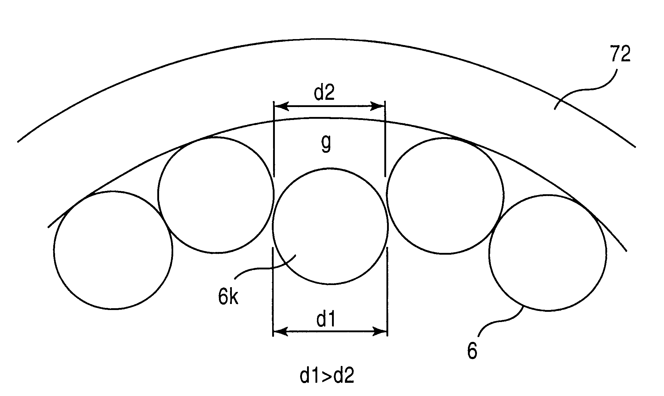
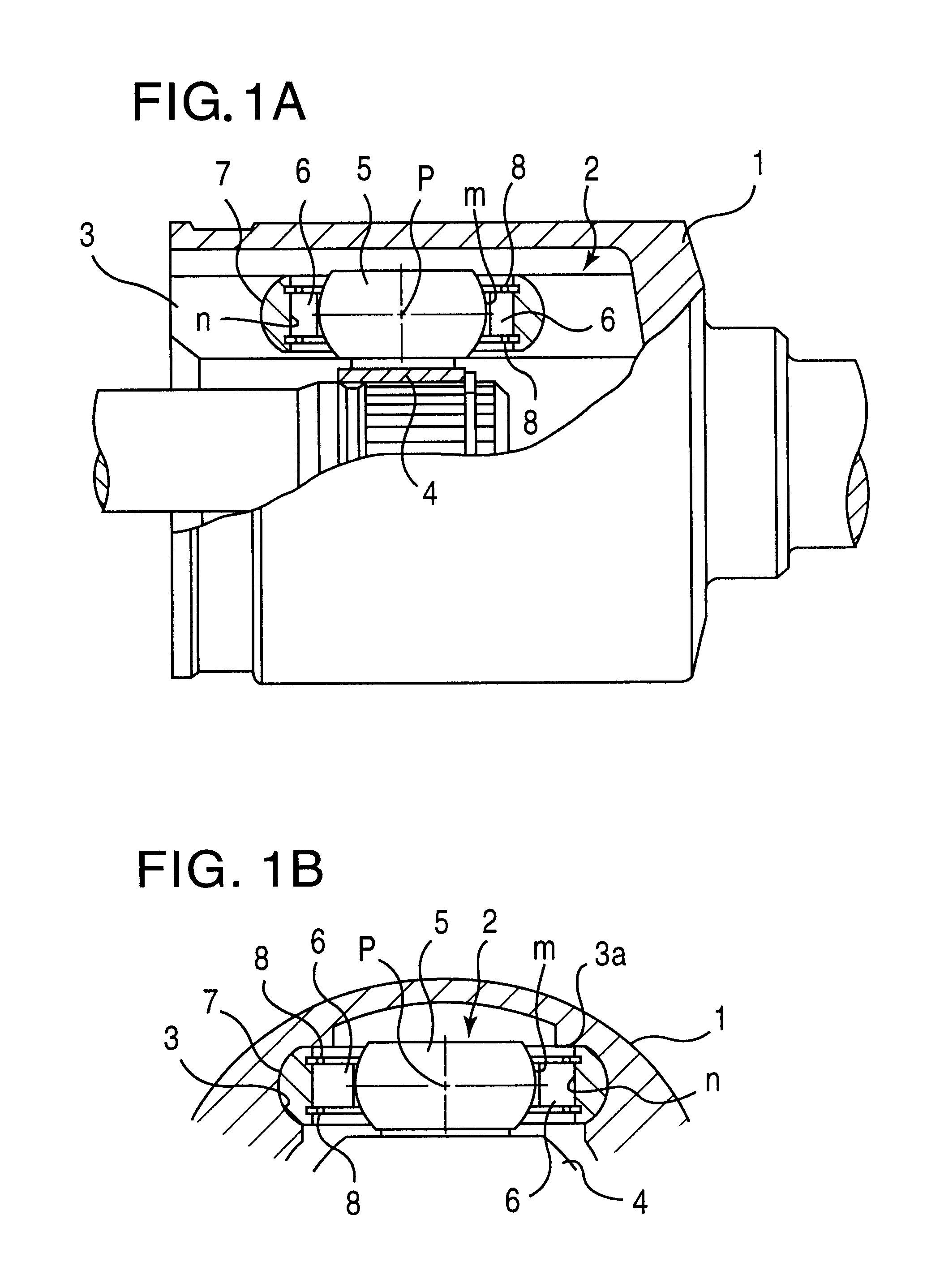
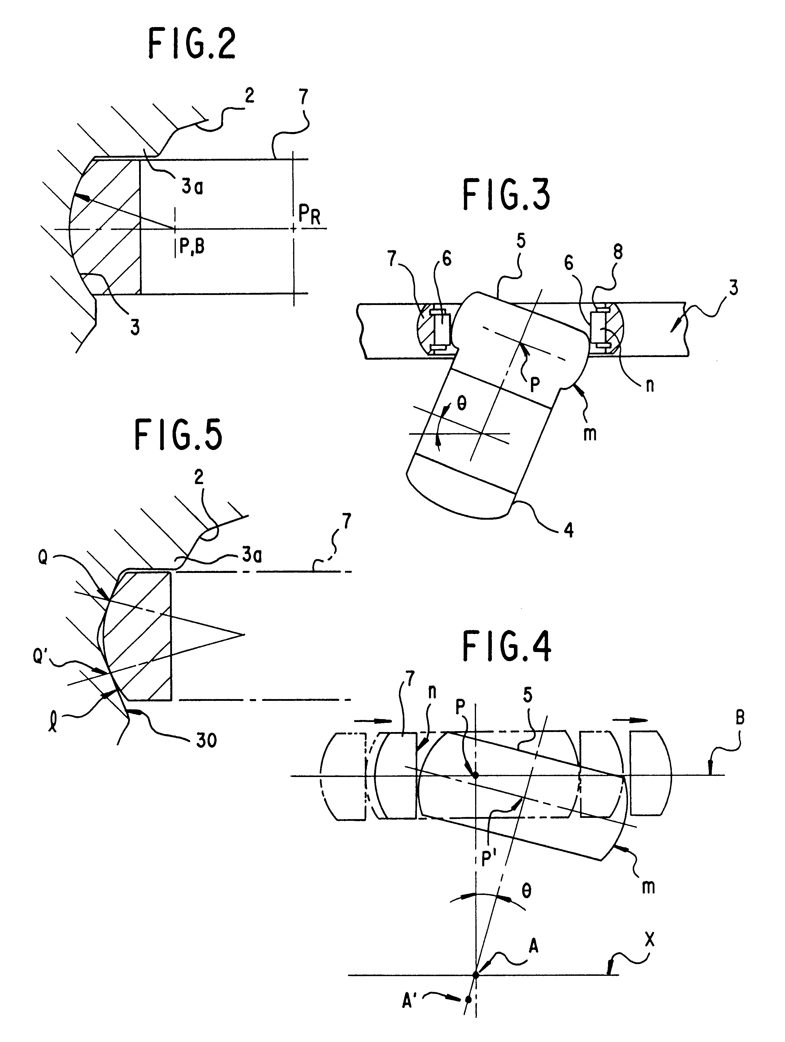
Referring first to FIGS. 1A and 1B, a tripod type constant velocity universal joint comprises an outer member 1 adapted to connect with one of two rotary axes being coupled together by the joint and a tripod member 4 adapted to connect with the other of the two axes. The outer member 1 is generally cup-shaped and has three circumferentially equispaced, axially extending track grooves 2 formed in an inner circumferential surface. The tripod member 4 has three circumferentially equispaced, radially protruding trunnions 5, each of which rotatably carries a roller 7 with rolling elements therebetween. The rollers 7 are respectively accommodated in the track grooves 2 of the outer member. The rollers 7 have cylindrical inner circumferential surface n which is fitted through the plurality of rolling elements 6 over an outer circumferential surface m of the trunnion, which surface m in turn is a part of a true sphere with its center p of curvature on the axis of the trunnion 5. As illustra...


PUM


Abstract

A tripod type constant velocity universal joint which includes an outer member having three axially extending track grooves formed in an inner circumferential surface thereof, each of the track grooves having roller guide surfaces on a pair of opposing side walls thereof, a tripod member having three radially projecting trunnions, and rollers rotatably carried on the trunnions, respectively, through a series of cylindrical rolling elements, the rollers being accommodated in the track grooves, respectively, so that the rollers are movable axially of the outer member with each said roller rolling along one of the opposing roller guide surfaces. The cylindrical rolling elements roll directly on an outer circumferential surface of the trunnion. Each said roller has an annular radial projection at each axial end thereof. The roller with the annular projections and a series of the rolling elements retained along an inner periphery of said roller form an independent assembly capable of preventing the rolling elements from dispersing prior to mounting the assembly on the trunnion.

Description

TECHNICAL FIELDThe present invention relates to a tripod type constant velocity universal joint which is applicable to front-wheel drive vehicles and others.BACKGROUND ARTIn front-wheel drive vehicles, as a constant velocity universal joint for transmitting torque from a drive shaft to front wheels at a constant velocity, there has been taken a joint of a tripod type as shown in FIGS. 8A and 8B. In this tripod type, a tripod member 4 has three radially protruding trunnions 11, which carry rollers 13 respectively rotatably fitted through rolling elements 12 over cylindrical outer circumferential surfaces of the trunnions 11, is inserted into an outer member 1 having three cylindrical track grooves 2 formed in an inner surface of and extending axially of the outer member 1. Each of the rollers 13 is accommodated in the corresponding track groove 2 so that it may travel along the track groove 2 rotating about an axis of the trunnion with an outer circumferential surface in engagement w...

Claims


Application Information

Patent Timeline
Patent Type & Authority Patents(United States)
IPC IPC(8): F16D3/205F16D3/16
CPCF16D3/2055
Inventor GOTO, TATUHIROSAITO, TSUYOSHIOZAWA, MASAHIRONAGATANI, HARUO
Owner NTN CORP
Why Eureka
Try Eureka