

Recuperator and radiant tube type heating apparatus
A technology of energy recovery and tubular heating, which is applied in lighting and heating equipment, burners, gas fuel burners, etc., can solve the problems of inability to adjust and achieve the effect of suppressing NOX
- Summary
- Abstract
- Description
- Claims
- Application Information
AI Technical Summary
Problems solved by technology
Method used
Image

Examples
Embodiment Construction
[0057] Hereinafter, an energy recovery device according to an embodiment of the present invention and a radiant tube heating device using the energy recovery device will be specifically described based on the drawings. In addition, the energy recovery device and the radiant tube type heating device using the energy recovery device of the present invention are not limited to the devices and equipment shown in the following embodiments, and can be implemented with appropriate changes within the range that does not change the concept of the invention. .
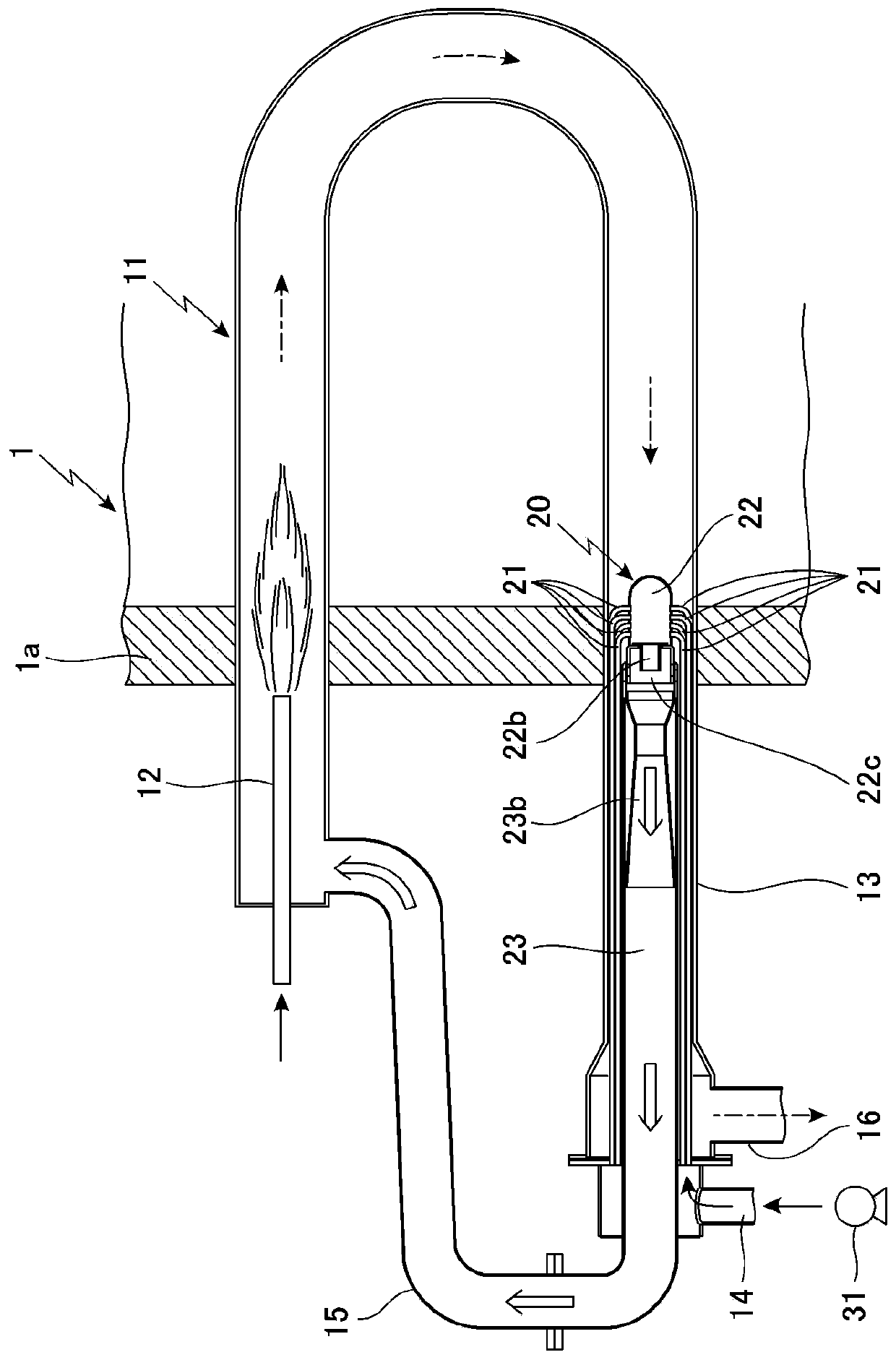
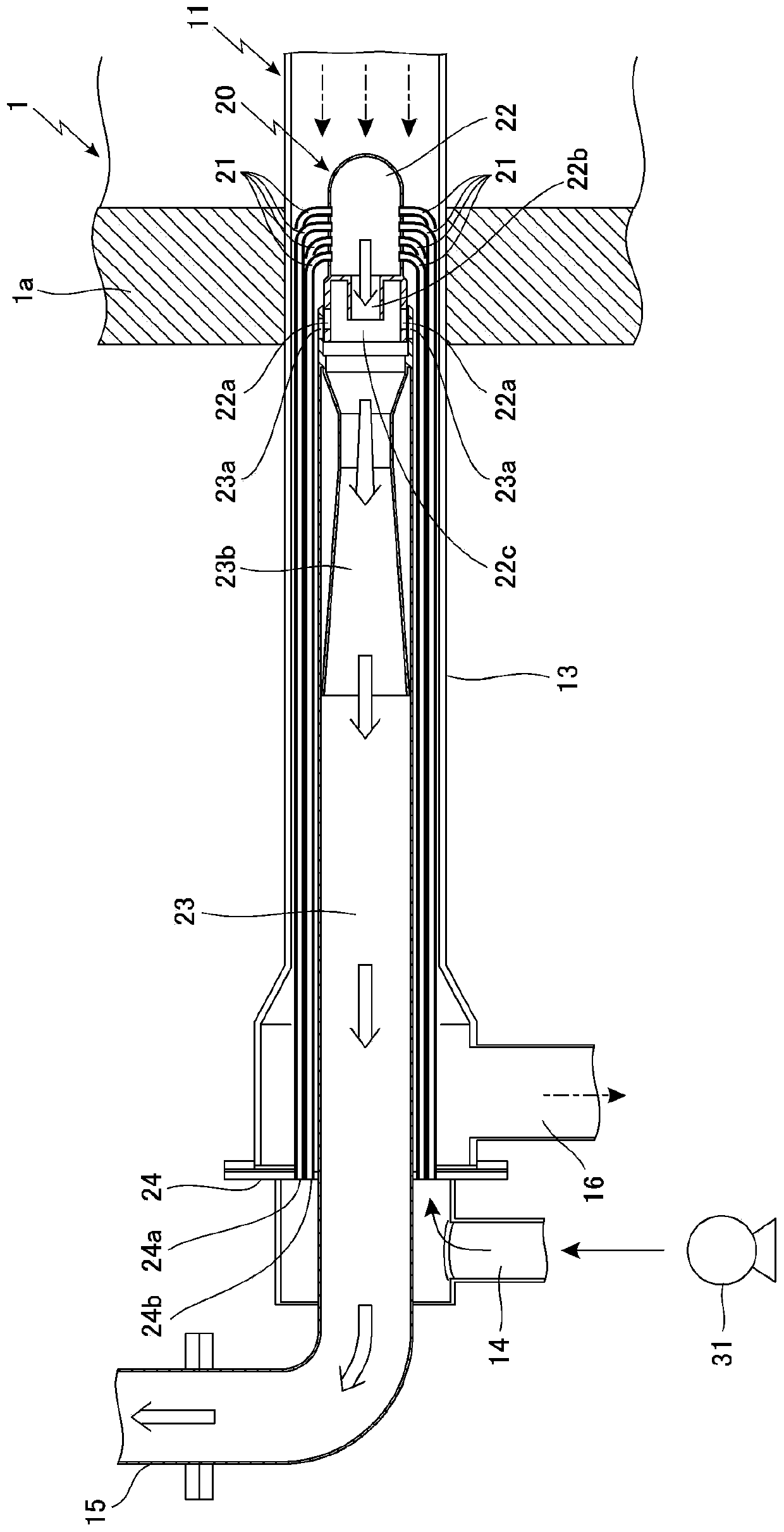
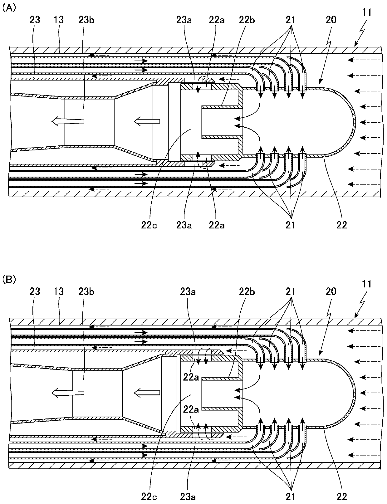
[0058] First, based on Figure 1 to Figure 4 (A) and (B) specifically describe the radiant tube heating device using the energy recovery device according to the embodiment of the present invention.
[0059] Here, if figure 1 As shown, in the above-mentioned radiant tube heating device, a U-shaped member is used as the radiant tube 11, and the U-shaped radiant tube 11 is arranged inside the industrial furnace 1. The two radiant...
PUM
 Abstract
Description
Claims
Application Information