
Temperature measuring device

A temperature measuring device and temperature measuring fiber technology, which is applied in the direction of measuring device, thermometer, measuring heat, etc., can solve the problem of unable to realize the simultaneous detection of multiple temperature measuring fibers, and achieve the effect of avoiding internal damage

Pending Publication Date: 2019-11-15
河北亿邦医疗设备股份有限公司
View PDF6 Cites 0 Cited by
  • Summary
  • Abstract
  • Description
  • Claims
  • Application Information

AI Technical Summary

Problems solved by technology

[0004] In view of this, the embodiment of the present invention provides a temperature measuring device to solve the problem that the existing temperature measuring device cannot realize the synchronous detection of multiple temperature measuring optical fibers

Method used


Image

  • Temperature measuring device
  • Temperature measuring device
  • Temperature measuring device

Examples


Embodiment Construction

[0037] In order to make the purpose, technical solutions and advantages of the embodiments of the present invention clearer, the technical solutions in the embodiments of the present invention will be clearly and completely described below in conjunction with the drawings in the embodiments of the present invention. Obviously, the described embodiments It is a part of embodiments of the present invention, but not all embodiments. Based on the embodiments of the present invention, all other embodiments obtained by those skilled in the art without creative efforts fall within the protection scope of the present invention.

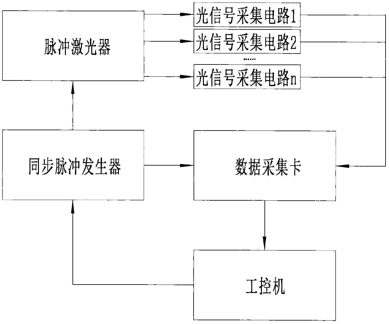
[0038] figure 1 A schematic structural diagram of a temperature measuring device in an embodiment of the present invention is shown. The temperature measuring device may include: an industrial computer, a synchronous pulse generator, a pulse laser, a data acquisition card, and multiple optical signal acquisition circuits with the same structure.

[0039] The...


PUM


Abstract

The invention discloses a temperature measuring device which comprises an industrial control computer, a synchronizing pulse generator, a pulse laser, a data collection card and multiple paths of light signal collection circuits in the same structure. The multiple paths of light signal collection circuits are connected in parallel between the output end of the pulse laser and the input end of thedata collection card; the synchronizing pulse generator is started by the industrial control computer, and sends synchronizing pulse signals to the pulse laser and data collection card. According to the temperature measuring device of the invention, the synchronizing pulse generator sends the synchronizing pulse signals to the pulse laser and data collection card at the same time, the pulse laserprovides light source used for temperature measurement for the light signal collection circuits, the data collection card synchronously receives scattered light data with temperature information fromthe optical signal collection circuits, and the problem that a present temperature measuring device cannot realize synchronous detection for multiple temperature measuring fibers is solved.

Description

technical field [0001] The invention relates to the technical field of temperature detection, in particular to a temperature measuring device. Background technique [0002] The existing technology can provide a variety of technical solutions to realize temperature measurement in an open space, such as non-contact infrared temperature detection technology and contact bimetallic temperature detection technology or thermistor temperature detection technology. However, infrared temperature detection technology is often inadequate for orientation or positioning detection in a narrow space. Since the infrared temperature detection device has a large volume, and it should be perpendicular to the surface of the object to be detected when measuring the temperature, it is inconvenient to use in a narrow space. Although bimetallic fiber optic temperature sensors and thermistor fiber optic temperature sensors used in bimetallic temperature detection technology or thermistor temperature...

Claims


Application Information

Patent Timeline
Patent Type & Authority Applications(China)
IPC IPC(8): G01K11/32
CPCG01K11/32
Inventor 段顺江孙洪利梁金生
Owner 河北亿邦医疗设备股份有限公司
Learn More