Device for measuring surface shape of high-reflection mirror

A measuring device and high-reflection technology, which is applied in the direction of measuring device, reflective surface test, optical device, etc., can solve the problems of surface shape accuracy, inaccurate results, filter lines, etc. The effect of sharpening and reducing intensity differences

Inactive Publication Date: 2019-11-15
MLOPTIC CORP
View PDF3 Cites 1 Cited by
  • Summary
  • Abstract
  • Description
  • Claims
  • Application Information

AI Technical Summary

Problems solved by technology

[0002] The problem encountered when measuring the surface shape of a high-reflection mirror with an ordinary flat standard mirror: when the incident light IO passes through the standard surface of the standard mirror, the reflected light IR is only 4% of the incident light IO, and the reflected light IR is only 4% of the incident light IO after passing through the standard mirror. Light It is 18~92% of incident light 10, and the intensity difference of two beams of reflected light is too big It ≥ 5IR like this, causes interference fringe very unclear (as Figure 4 shown), and cannot be fully analyzed, the results of such analysis are very inaccurate
Aiming at this problem, the solution currently adopted in the market is to add a filter in front of the standard lens. Although this method can clearly reflect the interference fringes, there will be lines of the filter on the entire interference surface (such as Figure 5 shown), so that the surface accuracy of the actual measured lens surface is affected by the filter

Method used


Image

  • Device for measuring surface shape of high-reflection mirror
  • Device for measuring surface shape of high-reflection mirror
  • Device for measuring surface shape of high-reflection mirror

Examples


Embodiment Construction

[0016] The present invention can be better understood from the following examples. However, those skilled in the art can easily understand that the content described in the embodiments is only for illustrating the present invention, and should not and will not limit the present invention described in the claims.

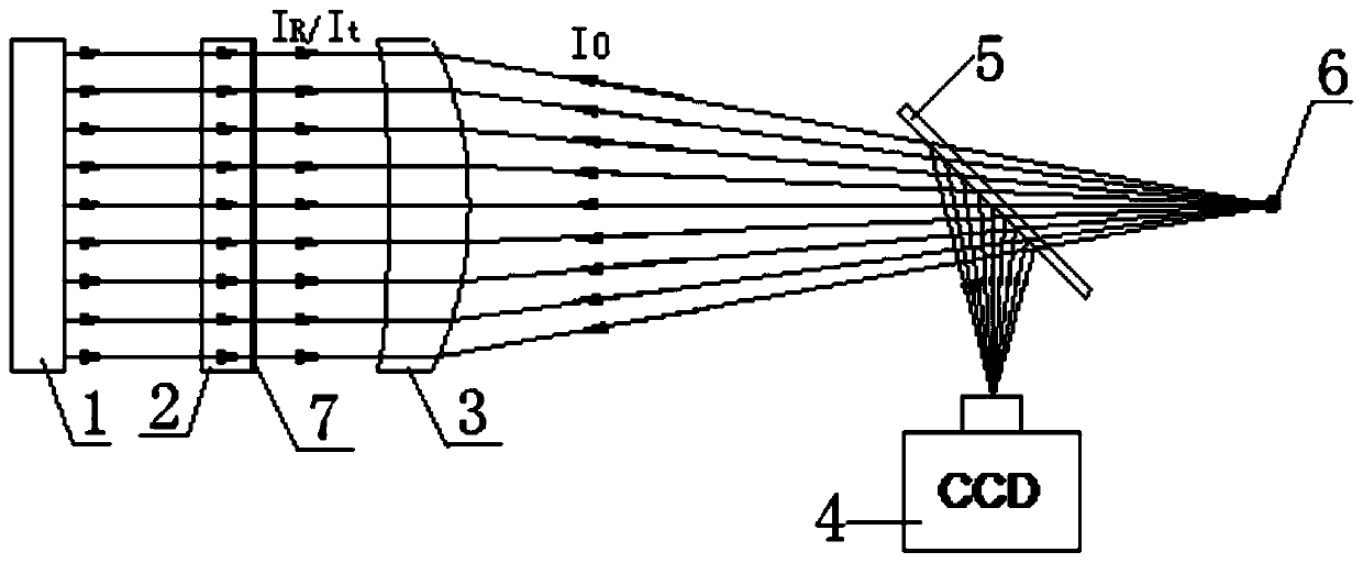
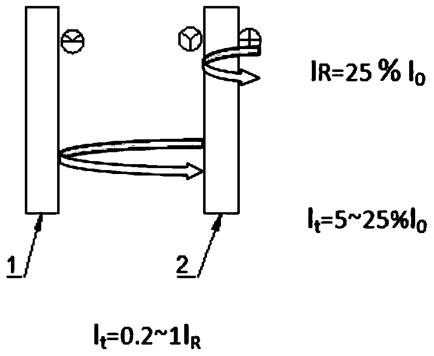
[0017] Such as figure 1 As shown, the measuring device of the high reflective mirror surface shape of the present invention comprises light source 6, beam splitter 5, collimator 3, standard mirror 2 and CCD imaging system 4; The front surface of standard mirror 2 is coated with spectroscopic film 7; Light source 6 emits After the light beam passes through the beam splitter 5, the point light source is converted into parallel light by the collimator 3. When the parallel incident light Io passes through the standard mirror 2, a part of the light is reflected back by the standard mirror 2 coated with the spectroscopic film 7 (for I R ), another part of the light reach...


PUM


Abstract

The invention discloses a device for measuring the surface shape of a high-reflection mirror. The device comprises a light source, a beam splitter, a collimator, a standard lens and a CCD imaging system. The front surface of the standard lens is plated with a light splitting film, a light beam emitted by the light source passes through the beam splitter and then is converted into parallel light bythe collimator, when the parallel incident light Io passes through the standard lens, part of the light is emitted is reflected and returned by the standard lens plated with the light splitting film,the other part of the light passes through the standard lens to arrive at the surface of the measured lens and is reflected by the surface of the measured lens, the light IR reflected and returned bythe standard lens plated with the light splitting film and light It reflected by the surface of the measured lens after passing through the standard lens form interference light and return the interference light to the beam splitter, the interference the light enters the CCD imaging system after being reflected by the beam splitter, and the intensity ratio It / IR of the two paths of coherent lightis 0.2-1.

Description

technical field [0001] The invention relates to a measuring device for the surface shape of a highly reflective mirror, which belongs to the technical field of imaging measurement. Background technique [0002] The problem encountered when measuring the surface shape of a high-reflection mirror with an ordinary flat standard mirror: when the incident light IO passes through the standard surface of the standard mirror, the reflected light IR is only 4% of the incident light IO, and the reflected light IR is only 4% of the incident light IO after passing through the standard mirror. Light It is 18~92% of incident light 10, and the intensity difference of two beams of reflected light is too big It ≥ 5IR like this, causes interference fringe very unclear (as Figure 4 shown), and cannot be fully analyzed, the results of such analysis are very inaccurate. Aiming at this problem, the solution currently adopted in the market is to add a filter in front of the standard lens. Althoug...

Claims


Application Information

Patent Timeline
Patent Type & Authority Applications(China)
IPC IPC(8): G01M11/02G01B11/24
CPCG01M11/025G01B11/2441G01M11/005G02B27/142G02B5/208G01B11/254G02B27/14G02B27/30
Inventor 宋治平
Owner MLOPTIC CORP
Why Eureka
Try Eureka