Infrared visual simulation platform construction method based on 3D engine and infrared visual simulation device

A 3D engine and visual simulation technology, applied in the field of infrared visual simulation platform, can solve the problems of long independent research and development cycle, high development cost, and difficulty in obtaining infrared simulation platform, so as to shorten the development cycle and cost, facilitate mass production and Easy-to-use, highly accessible effects

Pending Publication Date: 2019-11-15
哈尔滨新光光电科技股份有限公司
View PDF5 Cites 0 Cited by
  • Summary
  • Abstract
  • Description
  • Claims
  • Application Information

AI Technical Summary

Problems solved by technology

[0004] One purpose of the present invention is to solve the defects of the existing technology that the mid-infrared simulation platform is difficult to obtain, and the independent research and development cycle is very long and the development cost is high

Method used


Image

  • Infrared visual simulation platform construction method based on 3D engine and infrared visual simulation device
  • Infrared visual simulation platform construction method based on 3D engine and infrared visual simulation device
  • Infrared visual simulation platform construction method based on 3D engine and infrared visual simulation device

Examples


Embodiment Construction

[0018] Various exemplary embodiments of the present invention will now be described in detail with reference to the accompanying drawings. It should be noted that the relative arrangements of components and steps, numerical expressions and numerical values ​​set forth in these embodiments do not limit the scope of the present invention unless specifically stated otherwise.

[0019] The following description of at least one exemplary embodiment is merely illustrative in nature and in no way taken as limiting the invention, its application or uses.

[0020] Techniques, methods and devices known to those of ordinary skill in the relevant art may not be discussed in detail, but where appropriate, such techniques, methods and devices should be considered part of the description.

[0021] In all examples shown and discussed herein, any specific values ​​should be construed as exemplary only, and not as limitations. Therefore, other instances of the exemplary embodiment may have dif...


PUM


Abstract

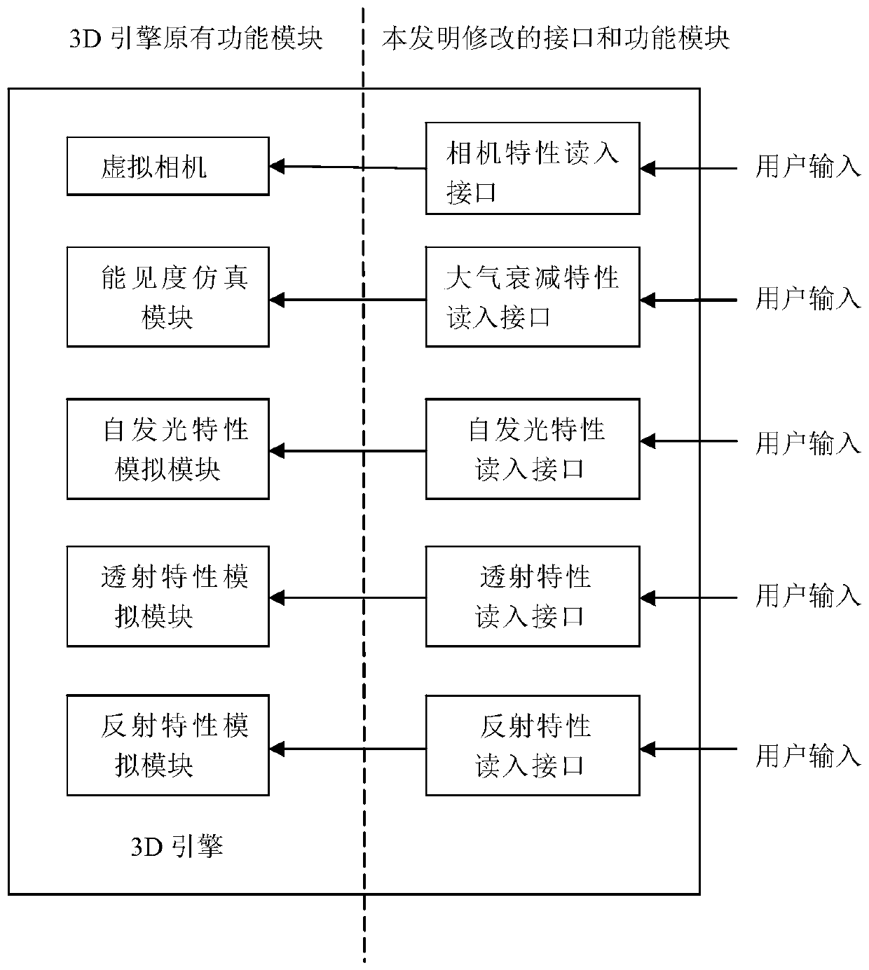
One purpose of the invention is to provide an infrared scene simulation platform construction method based on the 3D engine in order to solve the problem that an infrared simulation platform is difficult to obtain in the prior art, is long in independent research and development period and high in development cost. The method comprises the steps that a camera characteristic read-in interface is arranged in the 3D engine and used for determining the corresponding relation between the infrared scene gray scale and the infrared radiation brightness; an atmospheric attenuation characteristic read-in interface is arranged in the 3D engine and used for calculating atmospheric attenuation distribution; a self-luminous characteristic read-in interface is arranged in the 3D engine, wherein the self-luminous characteristic read-in interface is used for realizing self-luminous characteristic simulation of the object according to the input infrared band emissivity and the first correction coefficient; a transmission characteristic read-in interface is arranged in the 3D engine, wherein the transmission characteristic read-in interface is used for realizing transmission characteristic simulation of the object according to the input transmissivity and the second correction coefficient; and a reflection characteristic read-in interface is arranged in the 3D engine and is used for realizing infrared reflection characteristic simulation of the object according to the metallicity, the roughness and the spectral factor. The method and device are suitable for the field of infrared visual simulation.

Description

technical field [0001] The invention relates to the field of infrared visual simulation platforms, in particular to a construction method of an infrared visual simulation platform based on a 3D engine and an infrared visual simulation device. Background technique [0002] The infrared vision simulation platform is a necessary condition for generating infrared vision simulation software. The infrared image source provided by the infrared vision simulation software plays an important role in the optimization design of the infrared system, the performance evaluation of infrared optical equipment, and the auxiliary decision-making of the battlefield. It is of great strategic significance to enhance the research and development of infrared equipment. [0003] Foreign countries have strict export restrictions on infrared vision simulation platforms, making it difficult to obtain such software, and the cycle and development costs of independent research and development are very hig...

Claims


Application Information

Patent Timeline
Patent Type & Authority Applications(China)
IPC IPC(8): G06T17/00G06T15/06G06T15/50
CPCG06T15/06G06T15/506G06T17/00
Inventor 王艳春张崇毅刘珺琇
Owner 哈尔滨新光光电科技股份有限公司
Why Eureka
Try Eureka