Transparent display module and production method thereof

A technology of transparent display and manufacturing method, which is applied in the field of transparent display module and its manufacturing, can solve the problems of reducing brightness balance, poor conductivity of conductive glass, unfavorable application, etc., to achieve enhanced brightness balance, improve overcurrent capability, and realize large Dimensional effect

Pending Publication Date: 2019-11-15
厦门福相科技有限公司
View PDF0 Cites 7 Cited by
  • Summary
  • Abstract
  • Description
  • Claims
  • Application Information

AI Technical Summary

Problems solved by technology

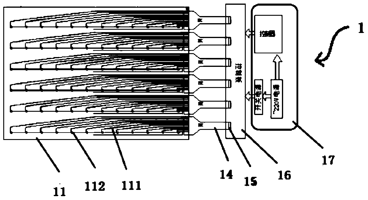
[0004] The conductive material commonly used in the above-mentioned transparent LED display is indium tin oxide (ITO), and the square resistance is about 20 ohms. The wiring should not be too thin or too long, otherwise the resistance will be very large
Therefore, as the size of the screen increases, the resistance value of indium tin oxide (ITO) will also increase, which is not conducive to practical applications.
In addition, conductive glass has poor conductivity, and as the size increases, the resistance of each line on the entire screen cannot be the same, resulting in uneven brightness of the screen; for example, if each row of an LED display has 12 lamp beads , then the width can only reach 40*12 = 480mm = 48cm, and each LED has three RGB signal lines, so a total of 12 *3 = 36 lines need to be drawn out. Under the 40mm spacing limit, each line The spacing is (40-7) / 36=0.9mm. It can be measured that the line resistance of the lamp bead (length 480mm, line distance 0.9mm) at the farthest end from the power supply can reach 10K ohms, while the most end lamp bead (length 40mm) , the line distance is 0.9mm) and the line resistance is about 1K ohms. In this case, if you directly supply power to the product, you will find that the brightness of the entire screen is uneven, the far FPC end is dark, and the near FPC is bright. The resistance makes the wire resistances of the farthest end and the closest end consistent, and it only takes the brightness of the lamp beads at the far FPC end as the standard, and reduces the brightness of the lamp beads at the near FPC end to achieve the brightness balance of the entire screen

Method used


Image

  • Transparent display module and production method thereof
  • Transparent display module and production method thereof
  • Transparent display module and production method thereof

Examples


Embodiment Construction

[0068] The implementation of the present invention is described below through specific specific examples, and those skilled in the art can easily understand other advantages and effects of the present invention from the content disclosed in this specification.

[0069] It should be noted that the structures, proportions, sizes, etc. shown in the drawings attached to this specification are only used to match the content disclosed in the specification, for those who are familiar with this technology to understand and read, and are not used to limit the implementation of the present invention. Therefore, it has no technical substantive meaning. Any modification of structure, change of proportional relationship or adjustment of size shall fall within the scope of the present invention without affecting the effect and purpose of the present invention. The disclosed technical content must be within the scope covered. At the same time, terms such as "above", "inner", "outer" and "a" ...


PUM


Abstract

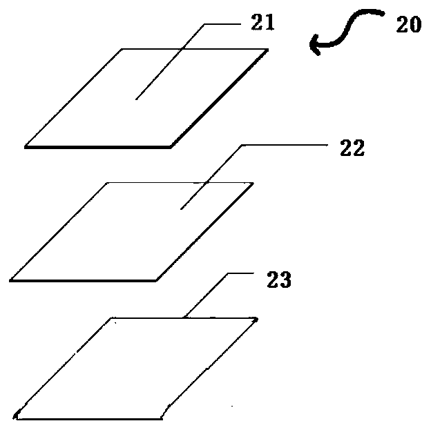
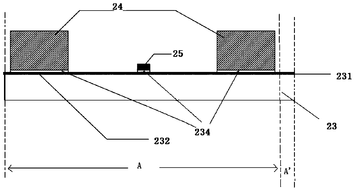
The invention discloses a transparent display module. The transparent display module comprises a first light-pervious layer, a second light-pervious layer and a middle layer arranged between the firstlight-pervious layer and the second light-pervious layer, wherein a conductive circuit layer is further arranged between the first light-pervious layer and the second light-pervious layer, beads arearranged on the conductive circuit layer, the conductive circuit layer is a metal grid conductive circuit, and the metal grid conductive circuit is electrically connected with the beads. The inventionfurther discloses a transparent display screen. The transparent display screen is formed by combining the transparent display modules. According to the transparent display module and the transparentdisplay screen, the metal grid conductive circuit is adopted, so that sheet resistance is low, and conductivity is better; and the luminance equilibrium of the LED display screen is enhanced, the transparency of a product is improved, and large size of the LED display screen is benefited.

Description

technical field [0001] The invention relates to a display device, in particular to a transparent display module and a manufacturing method thereof. Background technique [0002] With the development of LED technology, there are more and more products using LED technology. Conventional LED displays have high resolution and can be assembled into large-format display devices, so they are widely used in outdoor large-screen displays. Traditional outdoor LED screens are usually opaque, and are installed outside the outdoor building by hanging, which seriously affects the lighting of the building. [0003] In order to overcome the above-mentioned shortcomings of traditional LED screens, transparent LED screens emerged as the times require. The existing transparent LED display is usually to set LED lamp beads on the substrate, the substrate is covered with a film, and then covered with a cover to form a whole. The overall structure of the LED display includes the substrate, film,...

Claims


Application Information

Patent Timeline
Patent Type & Authority Applications(China)
IPC IPC(8): G09F9/33
CPCG09F9/33
Inventor 敖龙华吴辉荣
Owner 厦门福相科技有限公司
Why Eureka
Try Eureka