Load switch-fuse combination electric appliance and tripping device thereof
A technology for load switches and combined electrical appliances, applied in electrical switches, emergency protection devices, high-voltage air circuit breakers, etc., can solve problems such as hidden dangers of circuit safety, failure of tripping devices to trip normally, and phase-deficient operation of combined electrical appliances. The tripping force and the effect of increasing the displacement and increasing the driving force
- Summary
- Abstract
- Description
- Claims
- Application Information
AI Technical Summary
Problems solved by technology
Method used
Image

Examples
specific Embodiment approach
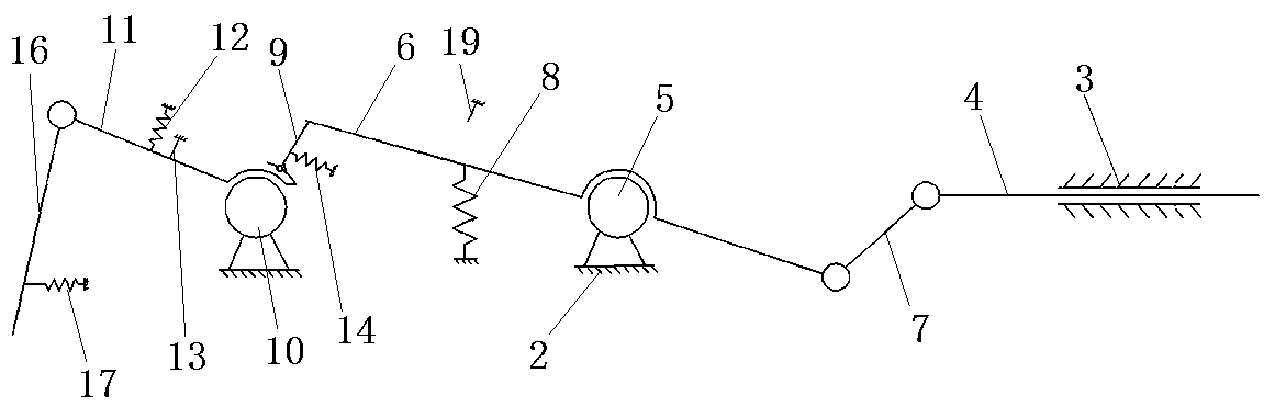
[0036] Such as figure 1 Shown is a simplified structural schematic diagram of a tripping device for a load switch-fuse combination in Example 1. The tripping device for a load switch-fuse combination (hereinafter referred to as the tripping device) includes a frame plate 2, a frame plate 2 There is a guide sleeve 3 on the top, and the guide sleeve 3 is equipped with a guide rod 4 extending along the length direction of the guide sleeve 3. The end of the guide rod 4 passing through the guide sleeve 3 is the trigger end for tripping. The guide rod 4 is used to guide the The sleeve 3 moves towards the direction of the operating mechanism of the load switch, so that the tripping trigger end triggers the micro switch (not shown) in the operating mechanism, so as to realize the tripping action of the tripping device and the opening of the corresponding load switch operate.
[0037] A microswitch trigger shaft (not shown) is also provided on the guide rod 4, and a microswitch (not s...
Embodiment 1
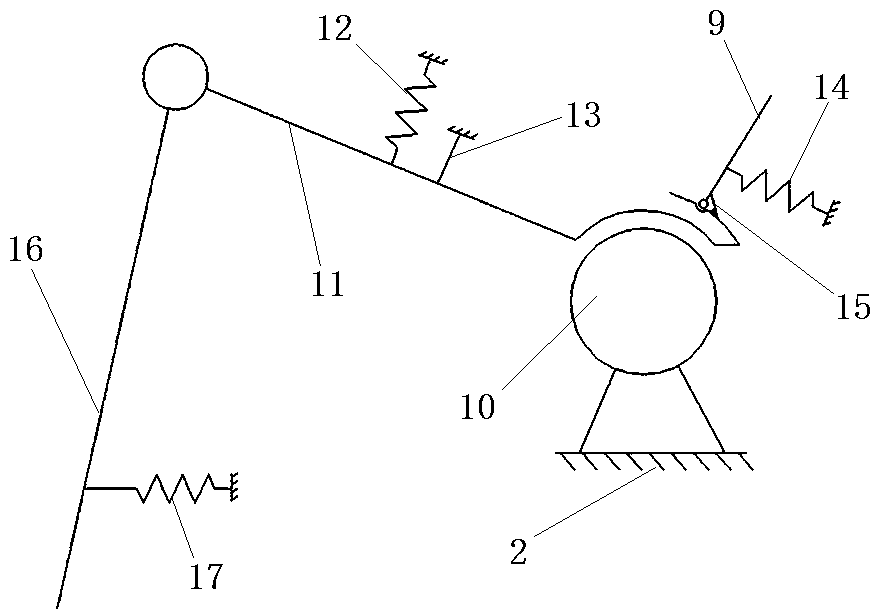
[0051] In Embodiment 1, since the locking piece 9 is hinged on the locking piece 11, the locking piece 9 can swing counterclockwise relative to the locking piece 11, and in the process of driving the driving piece to swing clockwise to push away the locking piece 9, the The driving member pushes away the locking member 9 to drive the locking member 9 to swing counterclockwise, thereby reducing the force of the operator to drive the driving member.
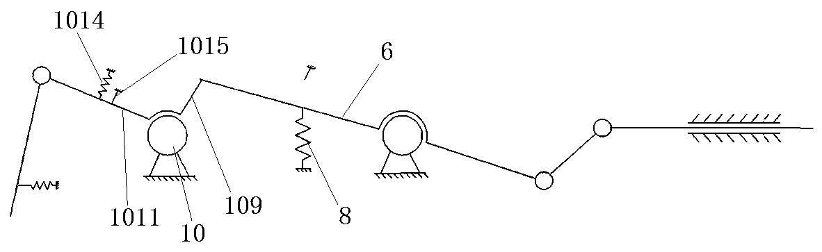
[0052] In Embodiment 2 of the load switch-fuse combined electrical appliance of the present invention, the difference from Embodiment 1 is: as image 3 As shown, the lock piece 109 can also be directly fixed on the chain piece 1011, the lock limit piece is not arranged between the lock piece and the chain piece, and the lock return spring is not arranged between the lock piece and the frame plate. , the locking return spring 1014 and the locking limiter 1015 can be arranged between the chain piece 1011 and the frame plate, or in ot...
PUM
 Abstract
Description
Claims
Application Information
 - Generate Ideas
- Intellectual Property
- Life Sciences
- Materials
- Tech Scout
- Unparalleled Data Quality
- Higher Quality Content
- 60% Fewer Hallucinations
Browse by: Latest US Patents, China's latest patents, Technical Efficacy Thesaurus, Application Domain, Technology Topic, Popular Technical Reports.
© 2025 PatSnap. All rights reserved.Legal|Privacy policy|Modern Slavery Act Transparency Statement|Sitemap|About US| Contact US: help@patsnap.com