Hydrogen recovery device of fuel cell system

A fuel cell system and recovery device technology, applied in the direction of fuel cells, fuel cell additives, electrical components, etc., can solve the problems of hydrogen leakage, easy damage of dynamic sealing elements, and reduce the power density of fuel cell engines, so as to reduce self-consumption Power, the effect of increasing power density

Pending Publication Date: 2019-11-15
苏州久安通氢能源科技有限公司
View PDF0 Cites 7 Cited by
  • Summary
  • Abstract
  • Description
  • Claims
  • Application Information

AI Technical Summary

Problems solved by technology

[0003] During the working process of the hydrogen fuel cell engine system, the remaining hydrogen gas discharged will be recovered for secondary recycling. In the prior art, a compression device driven by a high-speed motor is used for recovery. The power is 400-1000W, which will increase the fuel cell capacity. The self-consu

Method used


Image

  • Hydrogen recovery device of fuel cell system
  • Hydrogen recovery device of fuel cell system

Examples


Embodiment Construction

[0020] In order to make the object, technical solution and advantages of the present invention clearer, the present invention will be further described in detail below in combination with specific embodiments and with reference to the accompanying drawings. It should be understood that these descriptions are exemplary only, and are not intended to limit the scope of the present invention. Also, in the following description, descriptions of well-known structures and techniques are omitted to avoid unnecessarily obscuring the concept of the present invention.

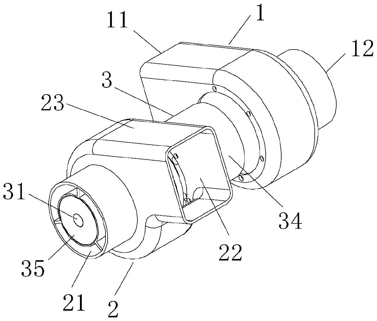
[0021] figure 1 It is a combination diagram of a fuel cell system hydrogen recovery device provided in this embodiment.

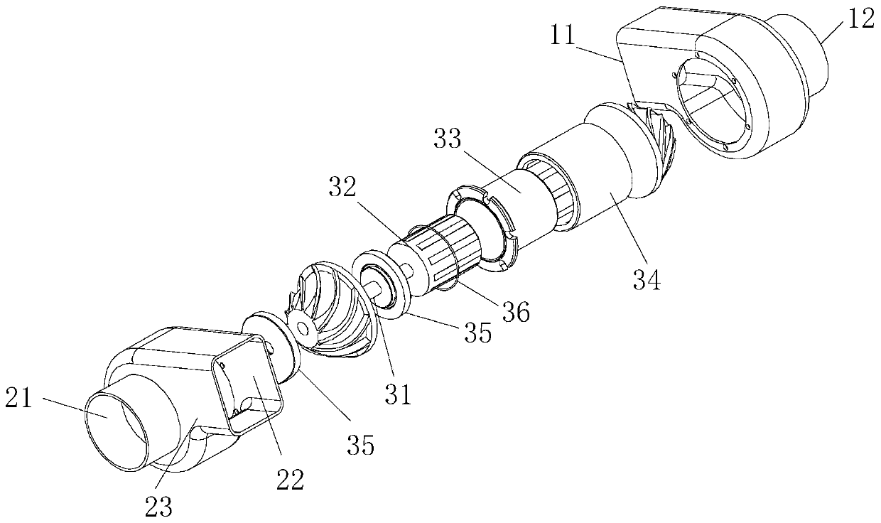
[0022] figure 2 It is an explosion diagram of a fuel cell system hydrogen recovery device provided in this embodiment.

[0023] like Figure 1-2 As shown, this embodiment provides a hydrogen recovery device for a fuel cell system, including a fuel cell, a turbine drive device 1 , a hydrogen compre...


PUM


Abstract

A hydrogen recovery device for a fuel cell system includes a turbine driving device provided with an air input port; a hydrogen compression device in driving connection with the turbine driving deviceand provided with a hydrogen inlet and a hydrogen outlet; and a fuel cell provided with a hydrogen input end, a hydrogen output end, an air input end and an air output end, wherein the hydrogen inputend of the fuel cell is communicated to the hydrogen outlet of the hydrogen compression device, the hydrogen output end of the fuel cell is communicated to the hydrogen inlet of the hydrogen compression device, and the air output end of the fuel cell is communicated to the air input port of the turbine driving device. By adopting the hydrogen recovery device of the fuel cell system, the self power consumption of the fuel cell engine is reduced. The power density of the fuel cell engine system is increased, and the net power output of the fuel cell is increased.

Description

technical field [0001] The invention relates to the technical field of hydrogen recovery, in particular to a hydrogen recovery device for a fuel cell system. Background technique [0002] A hydrogen fuel cell uses hydrogen as the fuel as the reducing agent, oxygen as the oxidant, and converts chemical energy into electrical energy through the combustion reaction of the fuel. When the hydrogen-oxygen fuel cell is working, hydrogen is supplied to the hydrogen electrode, and oxygen is supplied to the oxygen electrode at the same time. Under the action of the catalyst on the electrode, hydrogen and oxygen generate water through the electrolyte. At this time, there are excess electrons on the hydrogen electrode to be negatively charged, and the oxygen electrode is positively charged due to the lack of electrons. After the circuit is turned on, this reaction process similar to combustion can continue. [0003] During the working process of the hydrogen fuel cell engine system, ...

Claims


Application Information

Patent Timeline
IPC IPC(8): H01M8/0662H01M8/04082H01M8/04089H01M8/04111
CPCH01M8/04089H01M8/04097H01M8/04111H01M8/04201H01M8/0662Y02E60/50
Inventor 张硕张立芳孙柏刚王凤平
Owner 苏州久安通氢能源科技有限公司
Why Eureka
Try Eureka