Equipment system suitable for carbon dioxide cycle power generation using biomass as energy in rural areas

A technology of carbon dioxide and cycle power generation, which is applied in mechanical equipment, transportation and packaging, steam engine devices, etc., can solve the problems of unsuitable cycle power generation, high energy consumption of compressors, and large system investment, so as to achieve simple mechanism and reduce self-consumption energy, stable operating conditions and the effect of power output

Active Publication Date: 2019-01-22
长沙紫宸科技开发有限公司
View PDF4 Cites 0 Cited by
  • Summary
  • Abstract
  • Description
  • Claims
  • Application Information

AI Technical Summary

Problems solved by technology

[0004] The supercritical carbon dioxide power generation system developed with the application of CCS technology has significant advantages over traditional thermal power generation systems in terms of system thermal efficiency, total weight, floor area, and pollutant emissions, but there are still many bottlenecks in application. First, the high-efficiency heat exchanger of the existing supercritical carbon dioxide power generation system is the basis for the engineering application of the supercritical power generation system. Most of the heat exchange of the road uses a printed circuit board heat exchanger (PCHE), which is suitable for high working temperature and high working pressure, and has good expansion ability, which can meet the requirements of isobaric heating of carbon dioxide with a heat exchanger. However, the mechanism is complicated and the investment is large; secondly, the current supercritical carbon dioxide power generation system includes a heat source, a high-speed turbine, a high-speed generator, a high-speed compressor, and a cooler. The heat exchanger heats the carbon dioxide working medium at equal pressure—the working medium enters the turbine to drive the turbine to do work to drive the motor to generate electricity—the working medium enters the cooler—then enters the compressor to form a closed cycle, and the system investment is large; third, the current supercritical The carbon dioxide Brayton cycle requires the compressor parameters to be near the critical point to reduce the heat exchange end difference. The compression work of the compressor still accounts for more than 30% of the turbine output work during the compression process, and the compression work still accounts for more than 30% of the turbine output work during the actual compression process. 40% to 50% of the work, that is, the self-consumption energy of the compressor of the system is still relatively high; moreover, the high efficiency of the system cycle needs to be established when the carbon dioxide at the outlet of the condenser, that is, the suction inlet of the compressor (the starting point of the cycle) is still at 32°C , 7.4MPa at the critical point of the supercritical state, it is very difficult to control the operation state of the supercritical carbon dioxide power generation system, and control research still needs to be carried out
Obviously, the existing supercritical CO 2 Cyclic power generation technical solutions are not suitable for rural areas in my country

Method used


Image

  • Equipment system suitable for carbon dioxide cycle power generation using biomass as energy in rural areas
  • Equipment system suitable for carbon dioxide cycle power generation using biomass as energy in rural areas
  • Equipment system suitable for carbon dioxide cycle power generation using biomass as energy in rural areas

Examples


Embodiment 1

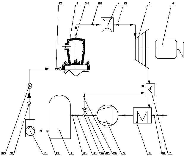
[0041] refer to figure 2 , one adopts 2 sets of boiling furnace CO 2 The equipment system of the energy storage device, mainly including liquid CO 2 Tank 1, CO 2 High-pressure pumping device 2, biomass furnace CO 2 Energy storage device 3, the second biomass furnace CO 2 Energy storage device 3′, steady flow regulator 4, turbine 5, generator 6, regenerator 7, cooler 8 and compressor 9, the liquid CO 2 The outlet of storage tank 1 is connected with CO through the first pipeline valve 101 2 The inlet of the high-pressure pumping device 2 is connected, and the CO 2 The outlet of the high-pressure pumping device 2 communicates with the first three-way valve 202 through the first check valve 201, the first three-way valve 202 communicates with the third three-way valve 203, and the third three-way valve 203 communicates with the third three-way valve 203 through the second pipeline valve 301. Biomass furnace CO 2 The inlet of the energy storage device 3 is connected, and th...

Embodiment 2

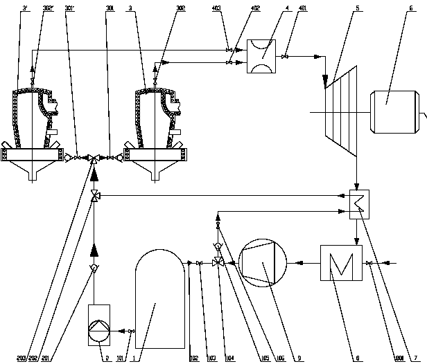
[0043] refer to image 3 , one featuring 2 sets of liquid CO 2 Storage tank + 3 sets of high pressure pumps + 3 sets of boiling furnace CO 2 The equipment system of the energy storage device, mainly including liquid CO 2 Storage tank 1, the second liquid CO 2 Storage tank 1ˊ, CO 2 High-pressure pumping device 2, the second CO 2 High-pressure pumping device 2ˊ, the third CO 2 High-pressure pumping device 2", biomass furnace CO 2 Energy storage device 3, the second biomass furnace CO 2 Energy storage device 3ˊ, third biomass furnace CO 2 Energy storage device 3", steady flow regulator 4, turbine 5, generator 6, regenerator 7, cooler 8 and compressor 9, the liquid CO 2 Storage tank 1, the second liquid CO 2The inlet of the storage tank 1' is connected through the second check valve 102, the seventh pipeline valve 103, the second three-way valve 104, the twelfth pipeline valve 103', and the third check valve 102', and the liquid CO 2 The outlet of storage tank 1 is conne...

Embodiment 3

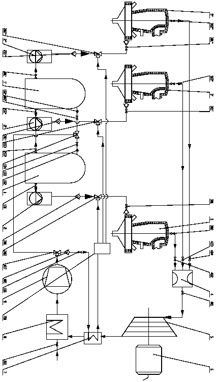
[0046] refer to Figure 4 , one using 2 sets of liquid CO 2 Storage tank + 2 sets of high pressure pumps for 2 sets of boiling furnace CO respectively 2 Energy storage device and 2 sets of grate furnace CO 2 The equipment system of the energy storage device, mainly including liquid CO 2 Storage tank 1, etc. 2 Liquid CO 2 Storage tank 1ˊ, CO 2 High-pressure pumping device 2, etc. two CO 2 High-pressure pumping device 2ˊ, boiling furnace CO 2 Energy storage device 3B, etc. 2 fluidized furnace CO 2 Energy storage device 3Bˊ, grate furnace CO 2 Energy storage device 3A, etc. the second grate furnace CO 2 Energy storage device 3A′, steady flow regulator 4, turbine 5, generator 6, regenerator 7, cooler 8 and compressor 9, the liquid CO 2 Storage tank 1, etc. 2 Liquid CO 2 The inlet of the storage tank 1' is connected through the second check valve 102, the seventh pipeline valve 103, the second three-way valve 104, the twelfth pipeline valve 103', and the third check valve...


PUM


Abstract

Applicable to the equipment system for rural carbon dioxide cycle power generation using biomass as energy, mainly including biomass furnace CO2 energy storage device, steady flow regulator, liquid CO2 storage tank, CO2 high-pressure pumping device, turbine / piston expander, generator , regenerator, cooler and compressor, the outlet of the liquid CO2 storage tank is connected to the inlet of the CO2 high-pressure pumping device, the outlet of the CO2 high-pressure pumping device is connected to the inlet of the CO2 energy storage device of the biomass furnace, and the CO2 storage device of the biomass furnace The outlet of the energy device is connected with the inlet of the steady flow regulator, the outlet of the steady flow regulator is connected with the inlet of the turbine / piston expander, the outlet of the turbine / piston expander is connected with the cooler through the regenerator, and the outlet of the cooler is connected with the compressor import connections. The invention has the advantages of being able to use the nearby large amount of renewable biomass resources in the countryside as energy, stable operation, low self-consumption energy, low investment, and low operating cost.

Description

technical field [0001] The invention relates to the field of low-carbon and energy technologies, in particular to an equipment system that uses carbon dioxide as a working medium and is suitable for rural carbon dioxide cycle power generation using biomass as an energy source. Background technique [0002] Climate change has become one of the issues that affect human survival and development, and a large amount of carbon dioxide emissions are considered to be the main cause of climate warming. As the largest developing country in the world, coal-based primary energy and firepower The secondary energy structure dominated by power generation, with the rapid growth of economic aggregate, the CO of primary energy and secondary energy 2 Emissions are characterized by rapid growth and large volumes. In response to climate change, the development of low-carbon energy, especially renewable energy and new energy, has become a consensus. Biomass power generation, solar power generatio...

Claims


Application Information

Patent Timeline
Patent Type & Authority Patents(China)
IPC IPC(8): F01K25/10F23N5/02B01F5/06B01F3/02B01F15/04B01F23/10
CPCF01K25/103F23N5/027B01F23/10B01F25/421B01F25/4233B01F25/422B01F25/4231B01F25/4522B01F35/883
Inventor 尹小林
Owner 长沙紫宸科技开发有限公司
Why Eureka
Try Eureka