Supercharge Your Innovation With Domain-Expert AI Agents!

Endscope system

A technology of endoscope and optical system, applied in the field of endoscope system, can solve the problems of smaller blur circle, narrower depth of field of camera device, etc.

Active Publication Date: 2019-11-15
OLYMPUS CORP
View PDF23 Cites 0 Cited by
  • Summary
  • Abstract
  • Description
  • Claims
  • Application Information

AI Technical Summary

Problems solved by technology

That is, in an imaging device, when the pixel pitch (the vertical and horizontal dimensions of one pixel) is reduced to increase the number of pixels, the allowable circle of confusion is also reduced accordingly, and thus the depth of field of the imaging device is narrowed.

Method used


Image

  • Endscope system
  • Endscope system
  • Endscope system

Examples


Embodiment A

[0077] (embodiment A, Figure 5 (a))

[0078] LiNbO 3 Single, d=0.17mm

[0079] λ / 4 wave plate that produces a phase difference of 27 wavelengths

Embodiment B

[0080] (embodiment B, Figure 5 of (b))

[0081] LiNbO 3 + glass, d = 0.06 (LN) + 0.24 (S-BSL7, made by Ohara Corporation) mm

[0082] Example of a λ / 4 wave plate that produces a phase difference of 10 wavelengths

Embodiment C

[0083] (embodiment C, Figure 5 of (c))

[0084] YVO 4 + glass, d = 0.2 (Y) + 0.2 (S-BSL7, made by Ohara Corporation) mm

[0085] Example of a λ / 4 wave plate that produces a phase difference of 85 wavelengths

[0086] Image 6 The structure of the endoscope system is shown. An endoscope system 1 according to the present embodiment includes an endoscope 2 inserted into a subject, a light source device 3 for supplying illumination light to the endoscope 2 , a processor device 4 , and an image display unit 5 .

[0087] The processor device 4 has a function of performing image processing, and also has other functions. The processor device 4 has an actuator control unit 25 , an image processor 30 , and a control unit 39 . The image display device 5 displays the image signal generated by the processor device 4 as an endoscopic image.

[0088] The endoscope 2 has an elongated insertion portion 6 to be inserted into the subject, and an operation portion 7 provided at the rear e...


PUM


Abstract

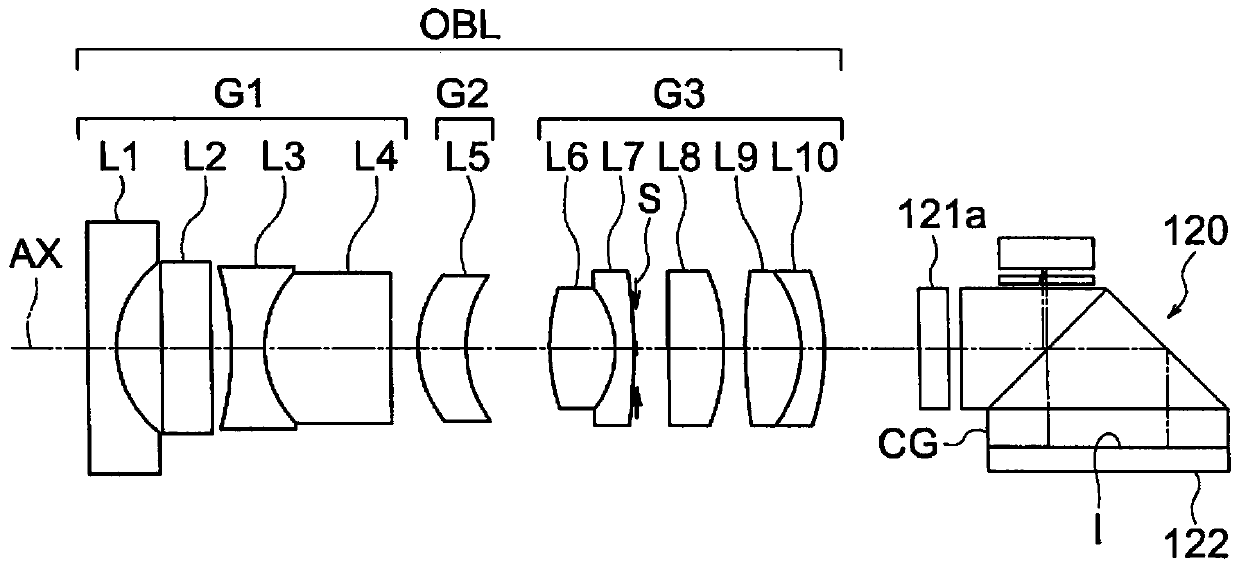
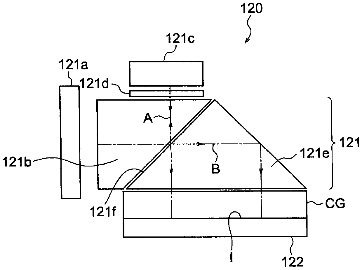
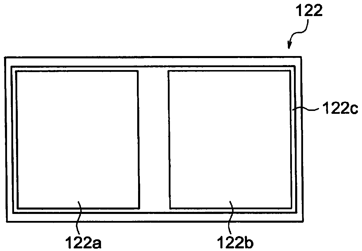
An objective of the present invention is to provide a compact endoscope system with which using a depolarization plate having a complex configuration is not required and it is possible to obtain an adequate depolarization effect. Provided is an endoscope system comprising, in order from the object side: an objective optical system OBL; an optical path segmenting unit 120 which segments light fromthe objective optical system in two; and an image capture element 122 which captures the two segmented images. A lambda / 4 wavelength plate 121a which is formed from one birefringent material is positioned in the optical path between the objective optical system OBL and the optical path segmenting unit 120. Said lambda / 4 wavelength plate 121a satisfies the following equations (1) and (2): 10 <= (d / d0) * 0.25 <= 85 (1) and 0.09 <= the absolute value of delta n <= 0.23 (2) where d is the thickness of the lambda / 4 wavelength plate, d0 is the thickness of the lambda / 4 wavelength plate which reacheszero order in a line e, and delta n is the refraction in the line e of the lambda / 4 wavelength plate.

Description

technical field [0001] The present invention relates to an endoscope system. Background technique [0002] It is generally known that in equipment including an imaging element such as an endoscope system, the depth of field becomes narrower as the number of pixels of the imaging element increases. That is, in the imaging device, when the pixel pitch (the vertical and horizontal dimensions of one pixel) is reduced to increase the number of pixels, the allowable circle of confusion is also reduced accordingly, and thus the depth of field of the imaging device is narrowed. [0003] In order to expand the depth of field, for example, a structure has been proposed in which a self-image is divided and imaged, and the obtained images are synthesized through image processing to expand the depth. Here, when the self-image is divided, it is efficient to use an optical path division unit using polarized light. In the optical path division unit using polarized light, it is desirable t...

Claims


Application Information

Patent Timeline
Patent Type & Authority Applications(China)
IPC IPC(8): A61B1/00G02B5/30G02B13/04G02B23/26H04N5/225
CPCG02B23/2446G02B5/3083G02B13/0065G02B27/0075A61B1/00096A61B1/00188A61B1/00186A61B1/05A61B1/07A61B1/00006A61B1/00009A61B1/045A61B1/00057H04N23/555G02B21/18H04N23/55
Inventor 露木浩
Owner OLYMPUS CORP
Features
  • R&D
  • Intellectual Property
  • Life Sciences
  • Materials
  • Tech Scout
  • Unparalleled Data Quality
  • Higher Quality Content
  • 60% Fewer Hallucinations
Learn More