A machine tool

A technology of machine tools and clamping mechanisms, applied in machine tool parts, metal processing machinery parts, processing and manufacturing, etc., can solve problems such as expensive and complicated pipelines

Inactive Publication Date: 2019-11-15
HYBRID MFG TECH LTD
View PDF7 Cites 3 Cited by
  • Summary
  • Abstract
  • Description
  • Claims
  • Application Information

AI Technical Summary

Problems solved by technology

[0011] It is understood that the buttable piping described on the treatment head and the piping corresponding to it are complex and expensive components
The effort required to install such a docking system is justifiable for laser-based directed energy source deposition of high-value components, often made of metal, but it has been realized that these components may not be suitable for processing heads due to cost etc. Certain combinations are used together, including the need to use certain types of inspection heads and other types of additive manufacturing techniques

Method used


Image

  • A machine tool
  • A machine tool
  • A machine tool

Examples


Embodiment Construction

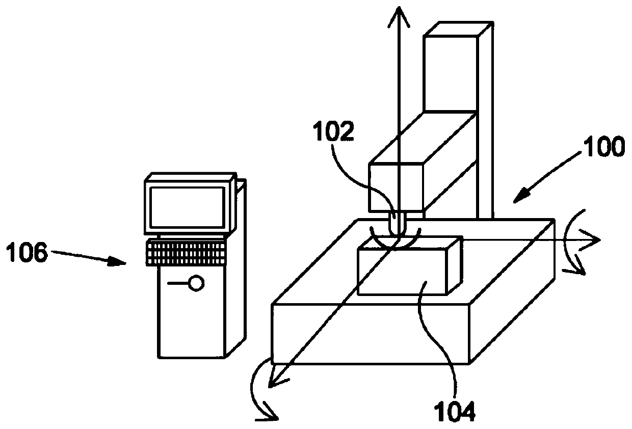
[0115] figure 1 is a schematic diagram of an exemplary automatic driving system according to some embodiments of the present application. In some embodiments, the machine tool 100 includes a clamping mechanism, a processing head 102 retained in the clamping mechanism, and the processing head 102 is configured to machine a workpiece 104 . In some embodiments, machine tool 100 is generally controlled by controller 106 , which controls the position of processing head 102 as processing head 102 processes workpiece 104 .

[0116] Most machine tools 100 are configured so that processing heads 102 are interchangeable with other processing heads 102 in order to provide the correct processing head 102 for the machining task at hand. Taking a milling machine as an example for illustration, the provided first processing head can be used for rough machining, and the provided second processing head can be used for finishing machining.

[0117] Correspondingly, in some embodiments, the ma...


PUM


Abstract

A machine tool (100) is arranged to deliver at least one of an energy source and a media, through a processing head (300) onto a work-piece for material addition, inspection or data collection, wherein the machine-tool has a clamping mechanism (202) arranged to temporarily receive the processing-head and wherein the machine tool comprises a stop block (390) having a manifold arranged to deliver atleast one of the energy and media and wherein the processing head comprises an anti-rotation arm (391) and connector (600) arranged to be connectable to the stop block and wherein the processing headfurther comprises a manifold arranged to engage with the stop block manifold when the processing head is connected to receive the energy or media. The machine tool may be a multi-axis machine tool and the stop block can be fixed to the machine tool or may be integrated therein.

Description

technical field [0001] The present application relates to a machine tool or other type of machine for delivering at least one of an energy source and a medium to a workpiece through a processing head. In particular, but not exclusively, the machine tool may be referred to as a hybrid machine tool. In particular, but not exclusively, the present application also relates to a device and a method of hybrid manufacturing using the same. [0002] Hybrid manufacturing refers to manufacturing methods that combine additive manufacturing and CNC machining. Background technique [0003] In the past, machine tools have been able to remove material from workpieces through so-called machining, which includes things like milling machines, often computer-controlled or computer numerical control (CNC). [0004] As stated in previous applications filed by the inventors, such as WO2014 / 013247 and WO2015 / 189600, conventional CNC milling machines, which may be referred to as "machine tools", ...

Claims


Application Information

Patent Timeline
Patent Type & Authority Applications(China)
IPC IPC(8): B29C64/106B29C64/153B29C64/209B29C64/118B23Q1/00B23K26/14B23K26/342
CPCB29C64/106B29C64/153B29C64/209B29C64/118B23Q1/0009B23K26/1482B33Y30/00B23K26/342B23K26/0093B23K26/702B22F2999/00B23Q2220/008Y02P10/25B22F12/44B22F12/50B22F10/25B22F12/90B22F10/22B22F3/227B29C64/188B23K28/02B23P23/04B23Q3/12B29C64/321B33Y40/20B23K26/34
Inventor 杰森·琼斯皮特·科茨皮特·乔恩·所罗门约书亚·泽德勒格
Owner HYBRID MFG TECH LTD
Why Eureka
Try Eureka