

Pot handle easy to adjust and disassemble
A pot handle and adjusting section technology, which is applied to household appliances, applications, kitchen utensils, etc., can solve the problem that the pot handle can not be detached and the length can be adjusted at the same time, and achieves a simple structure and operation method, low cost and convenient operation. Effect
- Summary
- Abstract
- Description
- Claims
- Application Information
AI Technical Summary
Problems solved by technology
Method used
Image

Examples
Embodiment 1
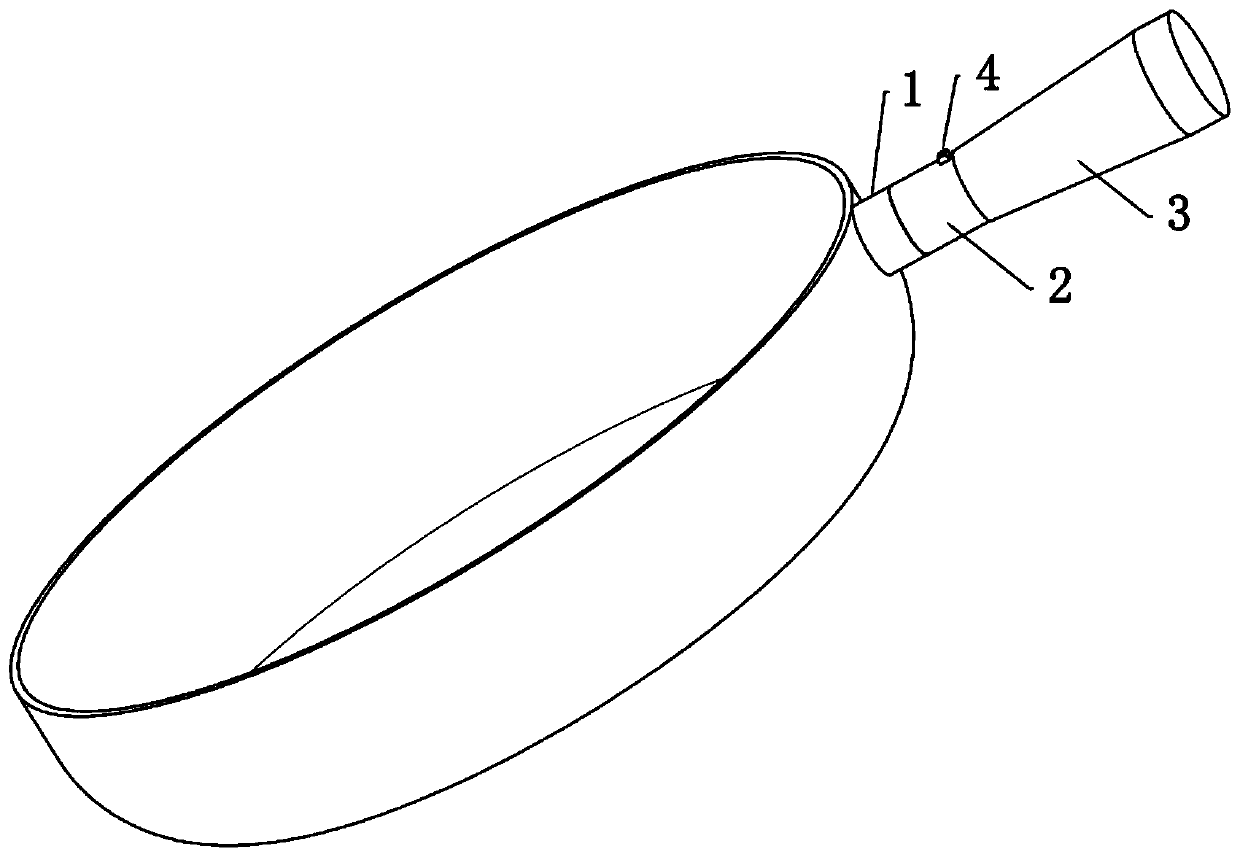
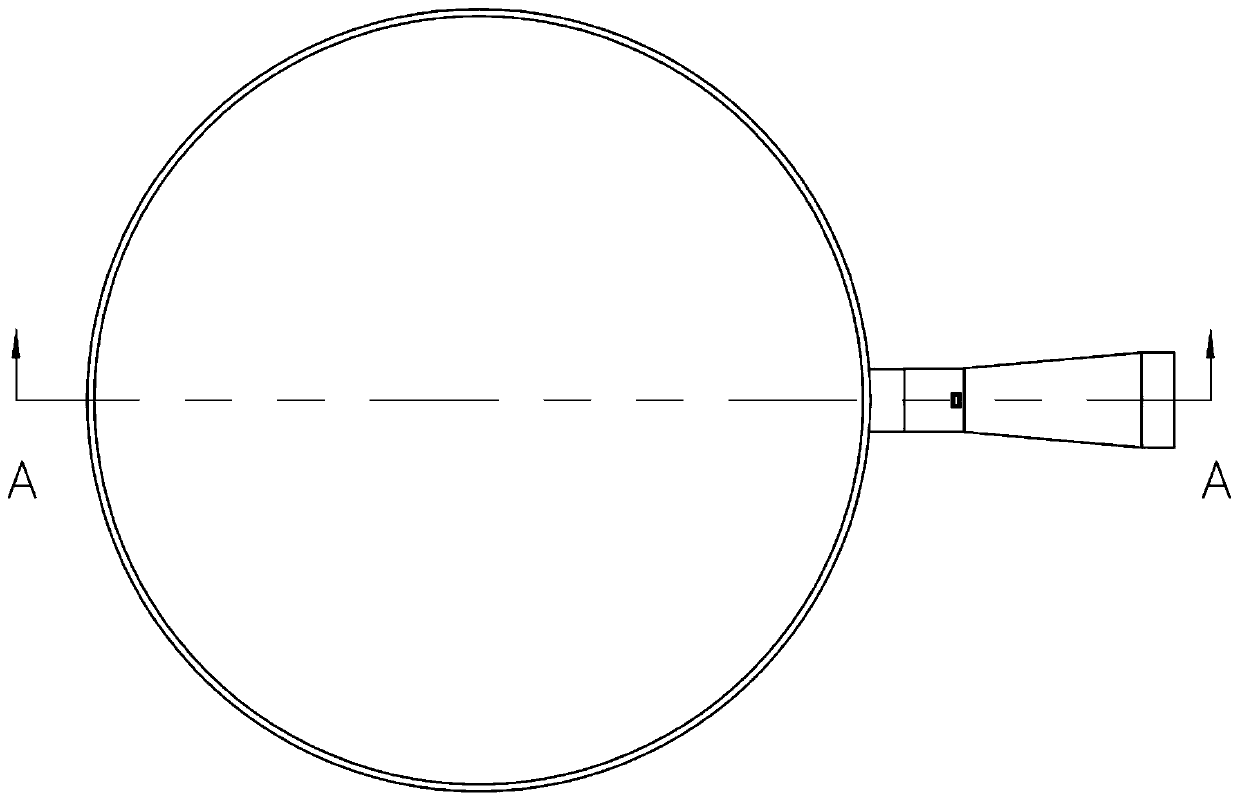
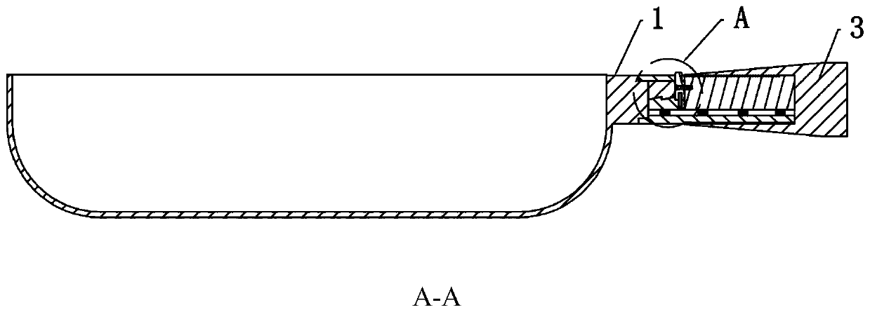
[0035] An easily adjustable and removable pot handle, cf. Figure 1-Figure 5 As shown, it includes a pot handle seat 1 fixed to the pot body and a pot handle body fixed to the pot handle seat 1. The pot handle body includes a fixed section 2 and an adjusting section 3 telescopically sleeved outside the fixed section 2. The fixed section 2 An engagement limit mechanism is arranged between the pot handle seat 1 and an adjustment limit mechanism is arranged between the fixed section 2 and the adjustment section 3 .
[0036] The bite limit mechanism includes a first bite block 6 protruding from the pot handle base 1 and a second bite block 7 that is raised and lowered inside the fixed section 2 and engages with the first bite block 6 .
[0037] Between the pot handle base 1 and the fixed section 2, there is a matching part that increases the fixing strength of the two. The plug-in block 5 provided between the blocks 6 fits snugly with the groove 201 , and the cross-sectional shap...
Embodiment 2
[0044] The bottom of the first snapping block 6 and the top of the second snapping block 7 are provided with triangular teeth, and the inclined surface of the triangular teeth of the second snapping block 7 is inclined away from an end of the first snapping block 6, and the triangular teeth of the first snapping block 6 The inclined surface of the inclined surface is provided obliquely away from an end of the second engaging block 7 .
[0045] When the pot handle base 1 and the fixed section 2 are fixed, automatic snapping and fixing can be realized without pressing the driving part. The specific operation is that when the second snapping block 7 is close to the first snapping block 6, the slopes between the two fit together, The inclined surface of the first engaging block 6 squeezes the inclined surface of the second engaging block 7 downwards, so that the second engaging block 7 gradually descends until the concavo-convex positions of the triangular teeth of the two are oppo...
Embodiment 3
[0047] The height of the teeth of the tooth block 8 and the rack 302 is consistent, the height of the triangular teeth of the first engaging block 6 and the second engaging block 7 is consistent, and the height of the teeth of the tooth block 8 and the rack 302 is smaller than that of the first engaging block 6 and the second engaging block 6. The height of the triangular teeth of the two engaging blocks 7 , the height of the teeth of the tooth block 8 and the rack 302 is preferably less than 1 / 2 of the height of the triangular teeth of the first engaging block 6 and the second engaging block 7 .
[0048] When the tooth block 8 and the rack 302 disengage from each other, the first engaging block 6 and the second engaging block 7 are still in the engaged state, and the length of the pot handle can be adjusted when the pot handle and the pot body are fixed.
PUM
 Abstract
Description
Claims
Application Information