Movable traction bed for lower limb fracture of child and control method of traction bed

A control method and a traction bed technology, applied in the field of medical care, can solve the problems of inability to detect fracture traction and reduction, difficulty in controlling fracture rotation and displacement, and the inability of the parents of children to return as soon as possible, so as to speed up the bed turnover rate and reduce hospitalization costs. , the effect of increasing family happiness

Pending Publication Date: 2019-11-19
杨淑野
View PDF0 Cites 4 Cited by
  • Summary
  • Abstract
  • Description
  • Claims
  • Application Information

AI Technical Summary

Problems solved by technology

[0006] 1) The existing adult orthopedic traction bed is too bulky, inconvenient to move, and difficult to nurse
[0007] 2) Long-term hospitalization is required to complete the treatment, and the parents of the child cannot return to work as soon as possible due to long-term bed companionship, increasing family pressure, increasing medical expenses, and affecting the family's sense of well-being
[0008] 3) The existing orthopedic window uses weights for traction, which cannot be precise and individualized, and there is a risk of lumps falling off
[0009] 4) Currently, the commonly used Brownian frame in clinic is the model used for adult fractures, which does not match the smaller body of children, and it is difficult to control the rotation and displacement of fractures
[0010] 5) The volume of the orthopedic traction bed is too large, it is inconvenient to move the patient, and it is inconvenient to review the image data during the treatment process, and it is easy to cause fracture displacement due to the movement, and it is impossible to show the reduction of the fracture after traction

Method used


Image

  • Movable traction bed for lower limb fracture of child and control method of traction bed
  • Movable traction bed for lower limb fracture of child and control method of traction bed
  • Movable traction bed for lower limb fracture of child and control method of traction bed

Examples


Embodiment 1

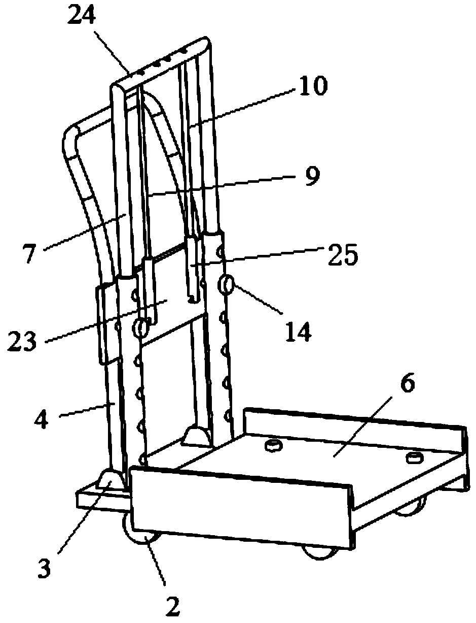
[0088] Embodiment 1: A movable children's lower limb fracture traction bed suitable for fractures in the middle part of the femoral shaft. Such as figure 1 shown.

[0089] The lower end of the base plate 1 is fixedly equipped with four universal wheels 2, and the upper end of the base plate 1 is fixedly equipped with a traction bed 6 by bolts, and both sides of the traction bed 6 are provided with baffles 23, which can effectively prevent the children being treated from being pulled. Bed 6 drops. The rear end of the base plate 1 is fixedly installed with a telescopic mounting frame 7, and the surface of the mounting frame 7 is provided with several mounting holes. The adjustment and fixation of the height of the mounting frame 7. The gantry 24 at the upper end of the two mounting brackets 7 is provided with several adjustment holes at intervals, the first traction rope 9 and the second traction rope 10 are passed through the adjustment holes, and are wound on the gantry 24,...

Embodiment 2

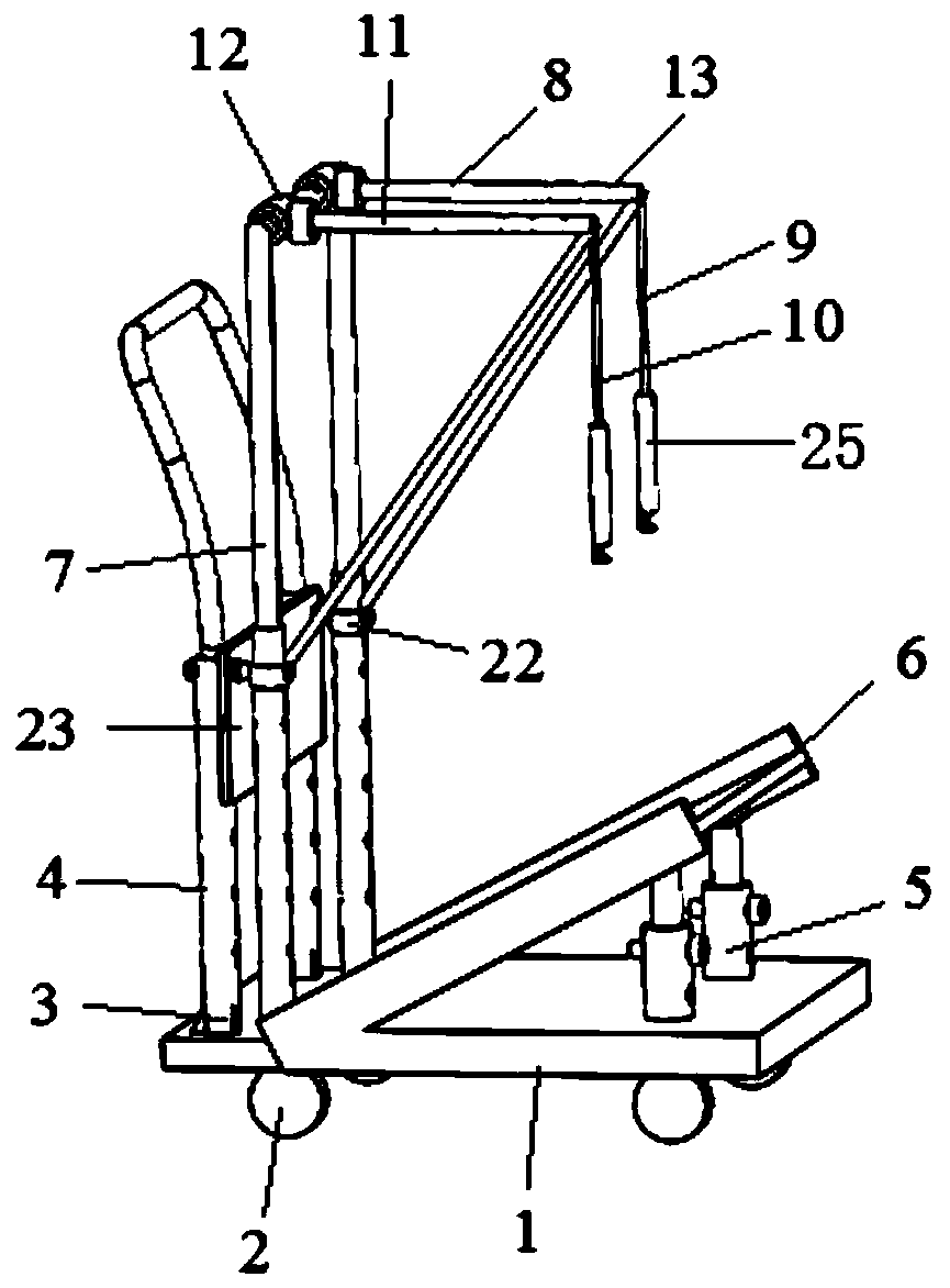
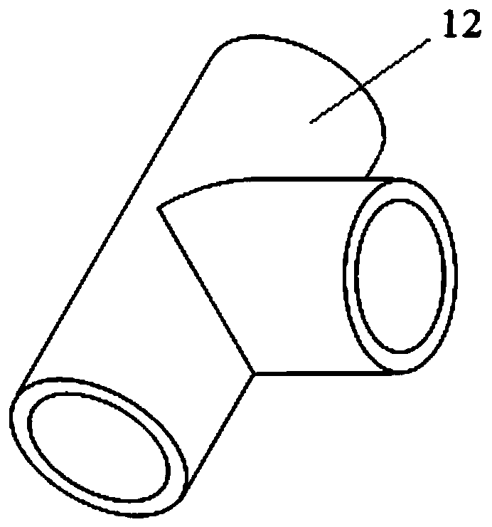
[0092] Embodiment 2: A movable children's lower limb fracture traction bed suitable for proximal femoral shaft fractures. Such as figure 2 , image 3 shown.

[0093] A traction bed 6 is fixedly installed on the bottom plate 1 through a liftable telescopic rod 5, and the inclination angle of the traction bed 6 can be tilted at different angles according to the different heights of the telescopic rod 5, which meets the needs of children patients. Four universal wheels 2 are fixedly installed on the lower end of the base plate 1 to facilitate the movement of the movable children's lower limb fracture traction bed 6 . The upper end of the base plate 1 is fixedly installed with a mounting frame 7, and the surface of the mounting frame 7 is provided with several mounting holes. adjustment and fixation. The upper ends of the two installation frames 7 are welded with a gantry frame 24, and two installation collars 12 are set on the gantry frame 24, and the first traction bracket ...

Embodiment 3

[0096] Embodiment 3: A movable children's lower limb fracture traction bed suitable for distal femoral shaft fractures. Such as Figure 4 , Figure 5 , Figure 6 .

[0097] The rear end of the base plate 1 is respectively fixedly equipped with an angle adjustment hinge support 3 and a mounting frame 7, and the angle adjustment hinge support 3 is fixedly installed with a handrail support 4, and the said handrail support 4 is provided with a number of mounting holes. A fixing device is fixedly installed in the mounting hole, and a crossbeam 20 is installed at the rear end of the fixing device. By adjusting the positions of the fixing device in different mounting holes, the height of the crossbeam 20 can be adjusted; thus the adjustment of the traction height can be realized. A pulley 21 is sleeved on the beam 20 . It is used to bolt the passing traction rope on the spring scale 25 for measuring the magnitude of the traction force.

[0098] The surface of the mounting frame ...


PUM


Abstract

The invention belongs to the technical field of medical care, and discloses a movable traction bed for a lower limb fracture of a child and a control method of the traction bed. The method comprises the following steps: a fracture traction direction is adjusted according to different fracture sites, a first traction rope and a second traction rope are hung on spring scales and pass through horizontal PVC pipe holes, the first traction rope and the second traction rope are pulled to lift a bearing platform away from a bottom plate, wherein in the adjustment of the fracture traction direction, fracture traction force values are displayed in real time through the spring scales. The movable traction bed for the lower limb fracture of the child provided by the invention has the advantages of asmall size, convenient movement, simple nursing and convenient re-hospitalization check; the hospital stay time is shortened, parents of the child can return to work as soon as possible, the family pressure is reduced, the medical costs are reduced, and the family happiness is increased; and when the movable traction bed for the lower limb fracture of the child is used, fracture traction directioncan be adjusted according to the different fracture sites, and the movable traction bed can fully meet the needs of traction treatment of fractures at corresponding sites.

Description

technical field [0001] The invention belongs to the technical field of medical care, and in particular relates to a movable traction bed for children's lower limb fractures and a control method. Background technique [0002] At present, the commonly used existing technology in the industry is as follows. Adult orthopedic traction beds are currently used for suspension traction of femoral shaft fractures in children. Adult orthopedic traction beds are bulky and heavy, and traction still uses weights for traction, which is difficult to individualize and accurately change. [0003] Femoral shaft fracture is a relatively common fracture in children, accounting for 1.4%-1.7% of orthopedic injuries in children. It is more common in men, and the incidence rate is 2.6 times that of women. Fractures showed a bimodal distribution, most common at age 2 (childhood) and 12 years (adolescence). Most childhood fractures are caused by low-energy injuries such as ground sports or falls, s...

Claims


Application Information

Patent Timeline
Patent Type & Authority Applications(China)
IPC IPC(8): A61F5/042
CPCA61F5/042
Inventor 杨淑野李芳芳杜刚强张锴贾龙
Owner 杨淑野
Why Eureka
Try Eureka