Auxiliary volleyball training device for sports
A training device and volleyball technology, applied in ball games, sports accessories, etc., can solve the problems that are not conducive to improving the training efficiency of sports personnel, achieve the effect of changing the serving angle, enhancing functionality, and improving training efficiency
- Summary
- Abstract
- Description
- Claims
- Application Information
AI Technical Summary
Problems solved by technology
Method used
Image

Examples
Embodiment 1
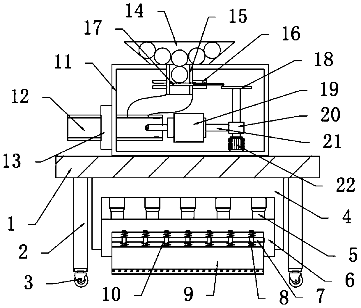
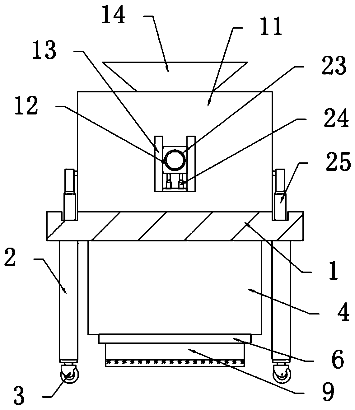
[0026] see Figure 1-3 , in an embodiment of the present invention, an auxiliary volleyball training device for sports, comprising a mounting plate 1, the bottom of the left and right ends of the mounting plate 1 are fixedly connected with support columns 2, and the bottom of the support column 2 is fixedly connected with casters 3. A lifting mechanism fixedly connected to the mounting plate 1 is provided between the support columns 2 on both sides, and a housing 11 is fixedly connected to the top of the mounting plate 1, and a lower ball mechanism is fixedly connected to the top of the housing 11 , the inner side of the housing 11 is provided with a ball-serving mechanism connected with the ball-down mechanism.
Embodiment 2
[0028] In this embodiment, the lower ball mechanism includes a lower ball bucket 14, a lower ball tube 15 and a limit block 16, the lower ball bucket 14 is fixedly connected to the top of the housing 11, and the bottom of the lower ball bucket 14 is fixedly connected A lower ball tube 15 is provided, the outer side of the lower ball tube 15 is fixedly connected with a limit block 16 fixedly connected with the housing 11, and the inner side of the limit block 16 is slidably connected with a baffle plate 17, and the baffle plate 17 The right end is connected with the drive mechanism, and by setting the lower ball mechanism, the volleyballs in the lower ball bucket 14 can be dropped into the ball outlet tube 12 one by one, so that the serving is more orderly.
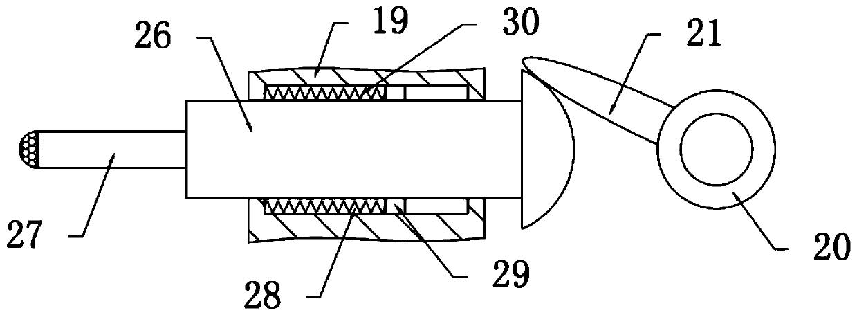
[0029] In this embodiment, the ball delivery mechanism includes a ball outlet tube 12 and a hitting mechanism. The ball outlet tube 12 is arranged on the left side of the housing 11, and the ball outlet tube 12 is connected...
PUM
 Abstract
Description
Claims
Application Information
 - R&D
- Intellectual Property
- Life Sciences
- Materials
- Tech Scout
- Unparalleled Data Quality
- Higher Quality Content
- 60% Fewer Hallucinations
Browse by: Latest US Patents, China's latest patents, Technical Efficacy Thesaurus, Application Domain, Technology Topic, Popular Technical Reports.
© 2025 PatSnap. All rights reserved.Legal|Privacy policy|Modern Slavery Act Transparency Statement|Sitemap|About US| Contact US: help@patsnap.com