Steel plate combined shear wall capable of achieving connection through crossed bending type partition board and preparing method

A combined shear wall and partition technology, applied in the direction of walls, building materials, building components, etc., can solve the problems affecting the overall strength of the steel plate combined shear wall, the difficulty in ensuring the quality of concrete pouring, and the long welding seam between the partition and the outer steel plate. and other problems, to achieve the effect of reducing welding residual stress, improving the quality of pouring and tamping, and improving the overall mechanical performance.

Pending Publication Date: 2019-11-19
THE ARCHITECTURAL DESIGN & RES INST OF ZHEJIANG UNIV
View PDF0 Cites 11 Cited by
  • Summary
  • Abstract
  • Description
  • Claims
  • Application Information

AI Technical Summary

Problems solved by technology

Existing steel plate composite shear walls are generally composed of two outsourcing steel plates and connectors on the outsourcing steel plates. When adopting discrete connectors or anchors arranged in a point shape, there is a problem of insufficient restraint on the outer steel plate, and the outer steel plate is prone to local buckling; when the diaphragm connector is used, the deformation of the outer steel plate is likely to occur when the diaphragm is welded. The installation accuracy of the partition is high, and the adjacent cavities formed by the partition are independent of each other, and concrete needs to be poured in each smaller cavity, which is inconvenient for construction and difficult to guarantee the quality of concrete pouring and tamping; moreover, The weld between the partition plate and the outer steel plate is long, and the residual stress is large, which will affect the overall strength of the steel plate combined shear wall

Method used


Image

  • Steel plate combined shear wall capable of achieving connection through crossed bending type partition board and preparing method
  • Steel plate combined shear wall capable of achieving connection through crossed bending type partition board and preparing method
  • Steel plate combined shear wall capable of achieving connection through crossed bending type partition board and preparing method

Examples


Embodiment 1

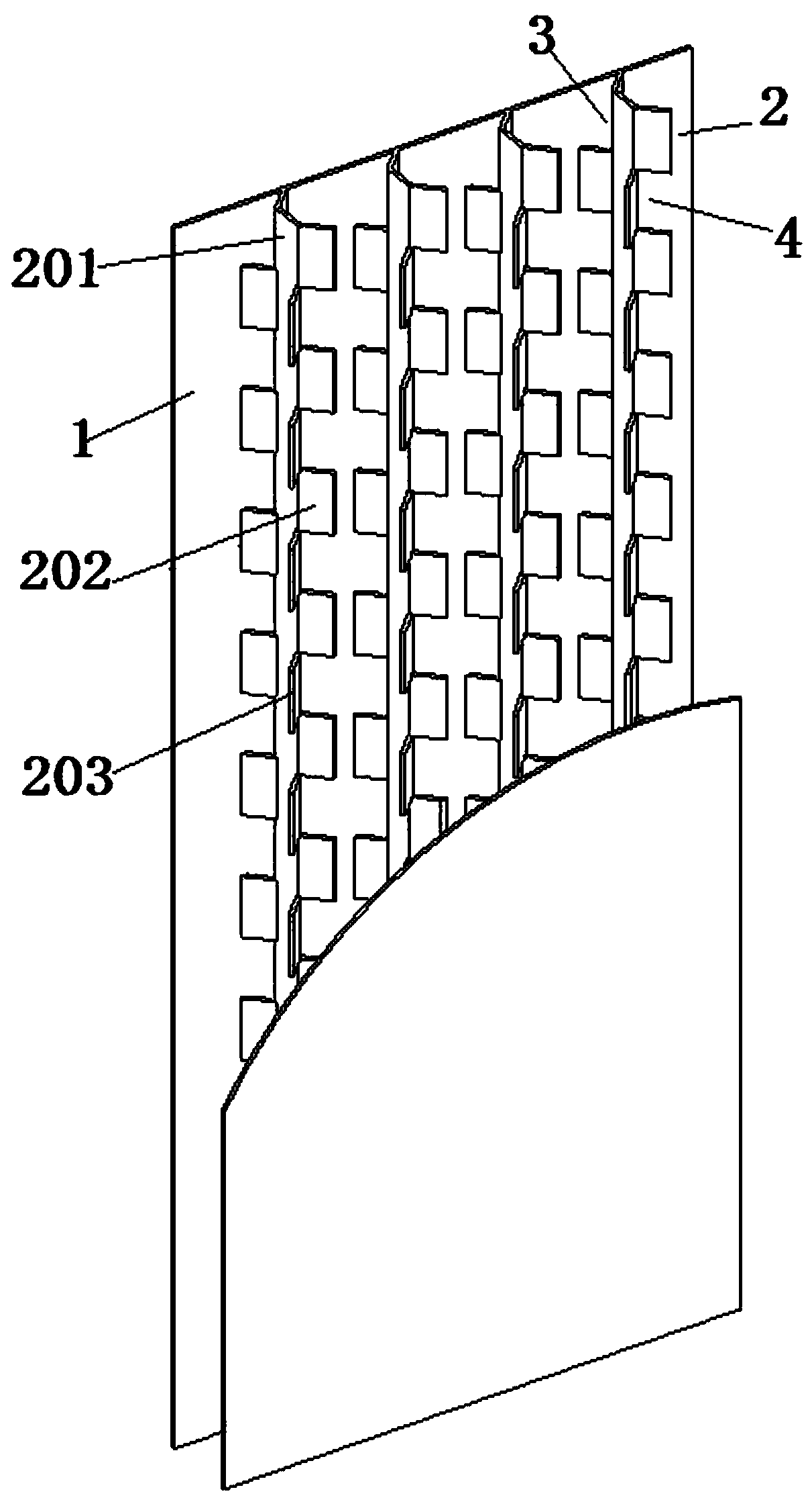
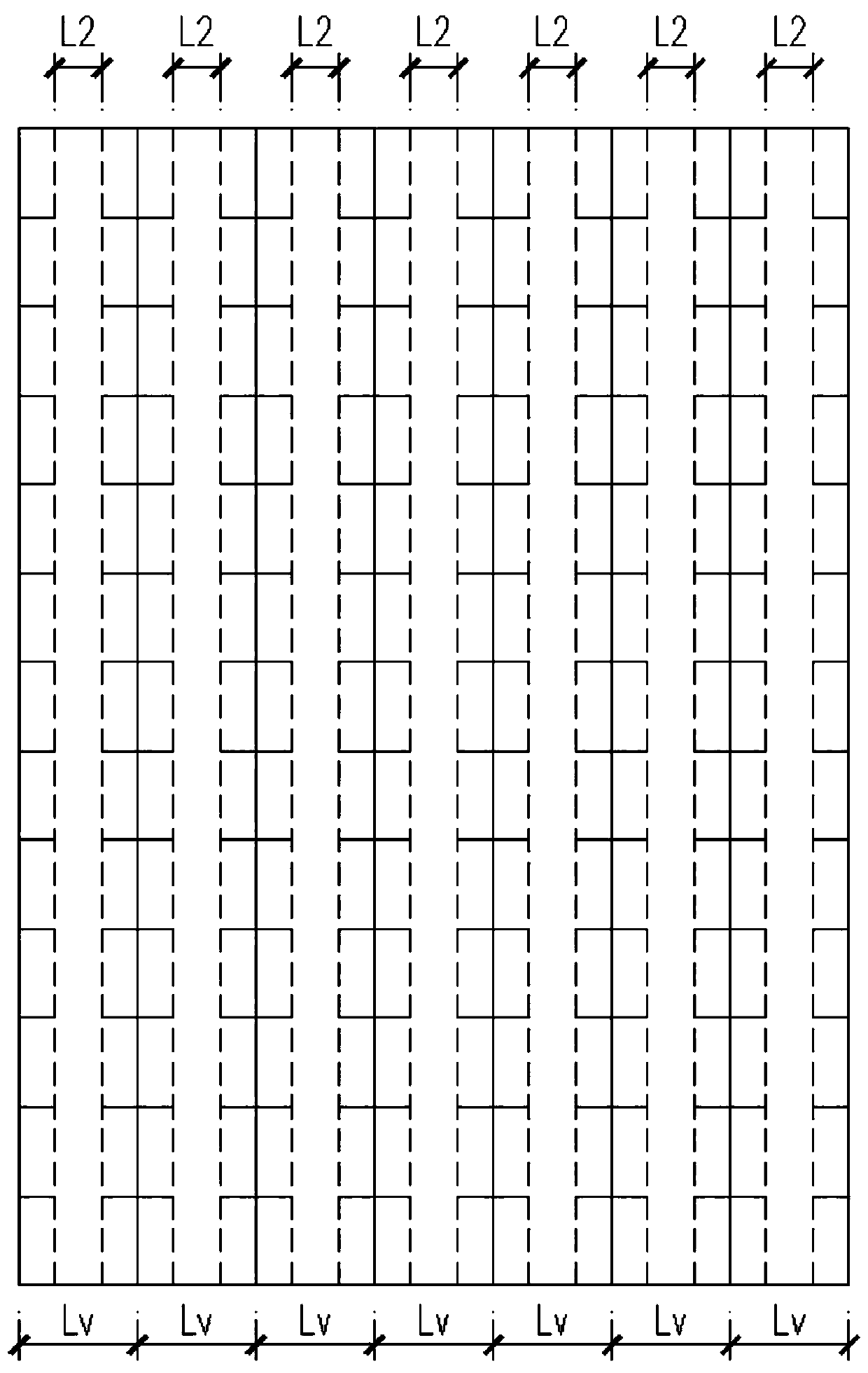
[0028] Example 1. A steel plate composite shear wall connected by cross-bending partitions, which is composed of Figure 1 to Figure 5 As shown, it includes two outsourcing steel plates 1 arranged in parallel, and a cross-bending partition plate 2 is arranged between the two outsourcing steel plates 1; between the cross-bending type partition plate 2 and the outsourcing steel plate 1, there are upper and lower alternately distributed first An opening 3 and a second opening 4 .

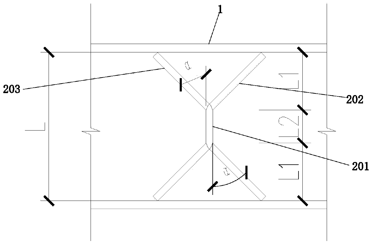
[0029] The cross-bending separator 2 includes a separator body 201, and a set of bending edge groups are arranged on both sides of the separator body 201; Two bent edges 203 .

[0030] Both sides of the partition body 201 are provided with groups of bent edges symmetrically distributed with each other.

[0031] The two sides of the partition body 201 are provided with groups of bent edges that are mutually offset. The first bending edges 202 on both sides of the partition body 201 are vertically st...

Embodiment 2

[0047] Example 2. A steel plate composite shear wall connected by cross-bending partitions, which is composed of Figure 2 to Figure 6 As shown, it includes two outsourcing steel plates 1 arranged in parallel, and a cross-bending partition plate 2 is arranged between the two outsourcing steel plates 1; between the cross-bending type partition plate 2 and the outsourcing steel plate 1, there are upper and lower alternately distributed first An opening 3 and a second opening 4 .

[0048]The cross-bending separator 2 includes a separator body 201, and a set of bending edge groups are arranged on both sides of the separator body 201; Two bent edges 203 .

[0049] Both sides of the partition body 201 are provided with groups of bent edges symmetrically distributed with each other.

[0050] The two sides of the partition body 201 are provided with groups of bent edges that are mutually offset. The first bending edges 202 on both sides of the partition body 201 are vertically sta...

Embodiment 3

[0065] Example 3. A steel plate composite shear wall connected by cross-bending partitions, which is composed of Figure 7 to Figure 8 As shown, it includes two outsourcing steel plates 1 arranged in parallel, and two cross-bending partitions 2 arranged side by side are arranged between the two outsourcing steel plates 1; The first openings 3 and the second openings 4 are distributed alternately up and down.

[0066] The cross-bending separator 2 includes a separator body 201, and a set of bending edge groups are arranged on both sides of the separator body 201; Two bent edges 203 .

[0067] Both sides of the partition body 201 are provided with groups of bent edges symmetrically distributed with each other.

[0068] The two sides of the partition body 201 are provided with groups of bent edges that are mutually offset. The first bending edges 202 on both sides of the partition body 201 are vertically staggered, and the opposite second bending edges 203 on both sides of th...


PUM


Abstract

The invention discloses a steel plate combined shear wall capable of achieving connection through a crossed bending type partition board and a preparing method. The wall comprises two parallel external package steel plates, the crossed bending type partition board is arranged between the two external package steel plates, and a first opening and a second opening which are alternatively distributedup and down are formed between the crossed bending type partition board and the external package steel plates. According to the steel plate combined shear wall, the quality of the steel plate combined shear wall can be effectively improved, and the whole stress property of the steel plate shear wall is improved.

Description

technical field [0001] The invention relates to a steel plate combined shear wall, in particular to a steel plate combined shear wall connected by cross-bending partition plates and a preparation method thereof. Background technique [0002] With the development of the industrialization of the construction industry, the traditional method of casting shear walls through formwork on the construction site has been gradually replaced by steel plate composite shear walls. Existing steel plate composite shear walls are generally composed of two outsourcing steel plates and connectors on the outsourcing steel plates. When adopting discrete connectors or anchors arranged in a point shape, there is a problem of insufficient restraint on the outer steel plate, and the outer steel plate is prone to local buckling; when the diaphragm connector is used, the deformation of the outer steel plate is likely to occur when the diaphragm is welded. The installation accuracy of the partition is...

Claims


Application Information

Patent Timeline
Patent Type & Authority Applications(China)
IPC IPC(8): E04C2/28E04C2/34E04B2/86
CPCE04B2/8629E04C2/28E04C2/3405
Inventor 李本悦肖志斌张明山夏亮杨嘉胤陈可鹏
Owner THE ARCHITECTURAL DESIGN & RES INST OF ZHEJIANG UNIV
Why Eureka
Try Eureka