Method and system for particulate filter regeneration

A particle filter, engine technology, applied in machine/engine, spark ignition controller, electronic control of exhaust treatment devices, etc., can solve problems such as undesired driving experience

Pending Publication Date: 2019-11-19
FORD GLOBAL TECH LLC
View PDF1 Cites 4 Cited by
  • Summary
  • Abstract
  • Description
  • Claims
  • Application Information

AI Technical Summary

Problems solved by technology

However, such indications can result

Method used


Image

  • Method and system for particulate filter regeneration
  • Method and system for particulate filter regeneration
  • Method and system for particulate filter regeneration

Examples


Embodiment Construction

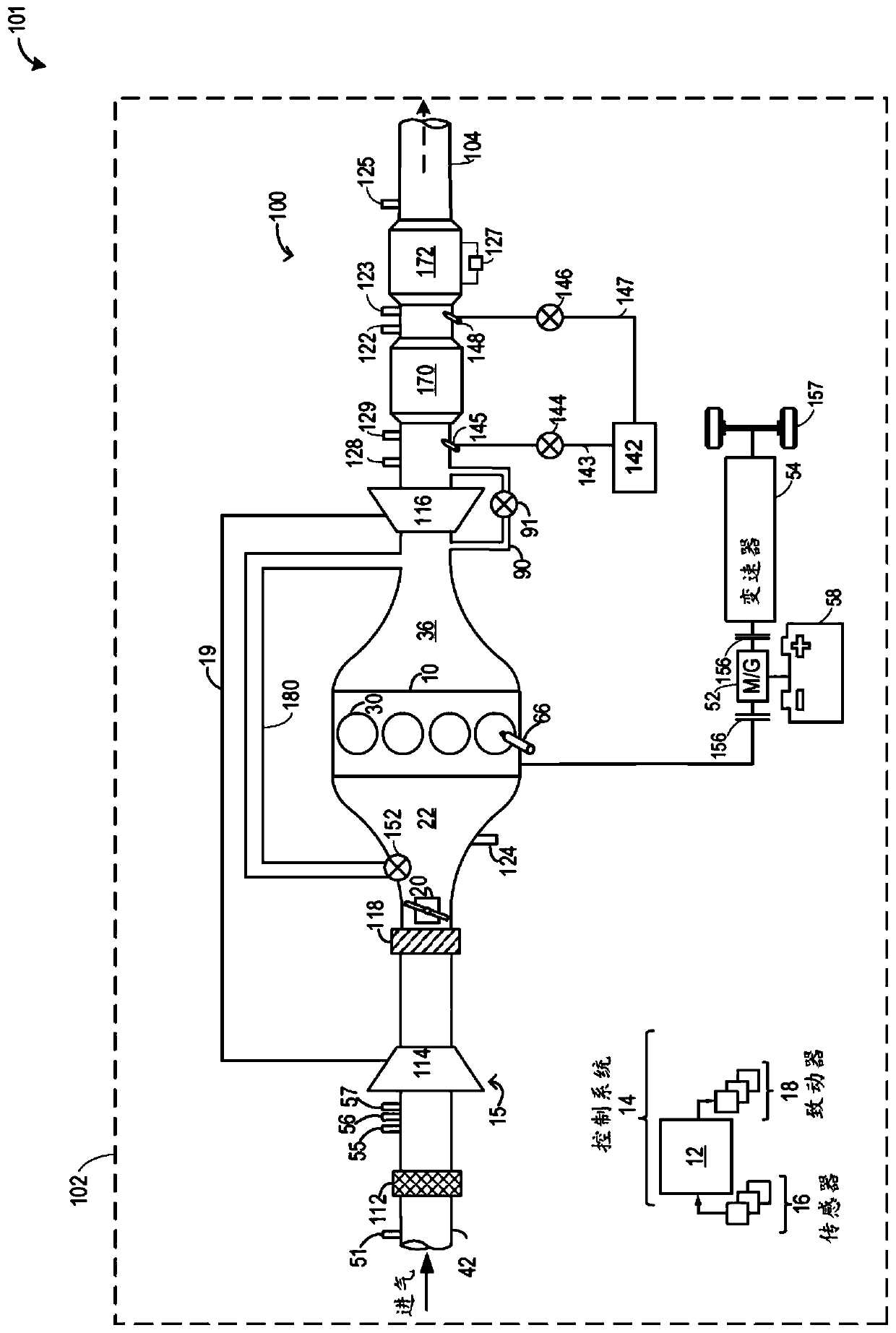
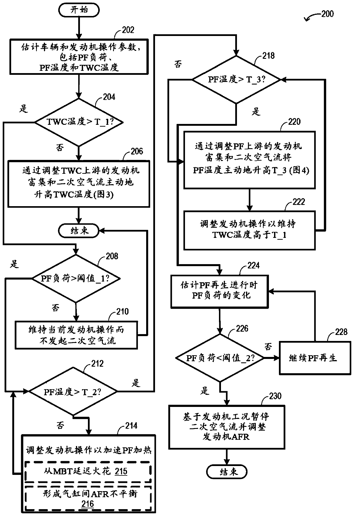
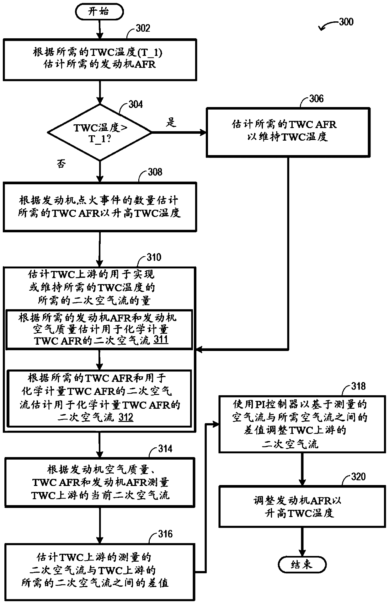
[0016] The following description relates to systems and methods for heating an exhaust particulate filter (PF) for filter generation. PF can be coupled to engine systems such as figure 1 The engine system of the engine system also includes an exhaust pump and one or more exhaust injectors to achieve accelerated heating of the PF and exhaust catalyst. The engine controller can be configured to execute control programs such as Figure 2 to Figure 4 An exemplary procedure for accelerating particulate filter heating to an operating temperature at which regeneration may be initiated while maintaining a catalyst temperature above a catalyst light-off temperature. Specifically, the controller may rely on heat release via engine air-fuel ratio adjustments enhanced using secondary air injection upstream of the PF and / or catalyst. Figure 5 A predictive example of coordinating secondary air injection with engine air-fuel ratio adjustments for PF heating and catalyst heating is shown. ...


PUM


Abstract

The present disclosure provides methods and systems for particulate filter regeneration. Methods and systems are provided for heating an exhaust particulate filter (PF) to enable filter generation. Inone example, a method may include adjusting engine air fuel ratio and injecting secondary air flow upstream of the PF to increase PF temperature. The level of engine air fuel ratio adjustment and theamount of secondary air injection upstream of the PF may be adjusted to account for enrichment induced cooling at a three-way catalyst (TWC) positioned upstream of the PF.

Description

technical field [0001] The present description generally relates to methods and systems for heating exhaust particulate filters for filter generation. Background technique [0002] Direct injection engines may provide enhanced performance such that engine efficiency may be improved. Injecting fuel directly into the cylinder reduces the temperature in the cylinder allowing more air and fuel to be drawn into the cylinder. However, the air-fuel mixture in the cylinder may not fully vaporize when fired at higher engine speeds and loads because there is not much time to mix the air with the fuel. As a result, a portion of the injected fuel may not be fully oxidized, thereby forming carbonaceous soot within the cylinder. After the soot is expelled from the engine, the soot may be stored in the particulate filter for subsequent oxidation. [0003] Some internal combustion engines employ a particulate filter or PF in the exhaust system (for example, a gasoline particulate filter ...

Claims


Application Information

Patent Timeline
IPC IPC(8): F01N3/029F01N9/00F01N3/22F01N3/32F01N3/20F02D41/02F02D41/14F02P5/15
CPCF01N3/0293F01N3/2033F01N3/22F01N3/222F01N3/32F01N9/002F02D41/008F02D41/0082F02D41/024F02D41/0255F02D41/029F02D41/1475F02P5/1502F01N3/025F01N3/101F01N3/225F01N3/30F01N2270/04F01N2430/06F01N2430/08F01N2560/025F01N2560/06F01N2560/14F01N2900/1404F01N2900/1602F01N2900/1606F01N2900/1626F01N13/009Y02T10/12F01N3/0234F01N3/035F01N2560/05
Inventor 约翰·罗林杰道格拉斯·马丁文森特·马丁内斯
Owner FORD GLOBAL TECH LLC
Why Eureka
Try Eureka