Hydraulic type piezoelectric-electromagnetic combined power generation system

A technology of electromagnetic composite and power generation system, which is applied in piezoelectric effect/electrostrictive or magnetostrictive motors, generators/motors, electrical components, etc. , Affect system integration design and other issues, achieve sustainable charging effect, contribute to integrated design, and simple structure

Inactive Publication Date: 2019-11-19
赵小龙
View PDF6 Cites 3 Cited by
  • Summary
  • Abstract
  • Description
  • Claims
  • Application Information

AI Technical Summary

Problems solved by technology

[0002] With the development of hydraulic technology, more and more sensors and micro-electromechanical systems are applied to hydraulic systems. However, the traditional power supply method supplies power to external power sources. Therefore, a large number of wires have to be inserted into the system, resulting in hydraulic pressure. The power lines of the system are complicated, which increases the difficulty of system installation and maintenance, and seriously affects the system integration design

Method used


Image

  • Hydraulic type piezoelectric-electromagnetic combined power generation system
  • Hydraulic type piezoelectric-electromagnetic combined power generation system
  • Hydraulic type piezoelectric-electromagnetic combined power generation system

Examples


Embodiment Construction

[0021] The following will clearly and completely describe the technical solutions in the embodiments of the present invention with reference to the accompanying drawings in the embodiments of the present invention. Obviously, the described embodiments are only some, not all, embodiments of the present invention. Based on the embodiments of the present invention, all other embodiments obtained by persons of ordinary skill in the art without making creative efforts belong to the protection scope of the present invention.

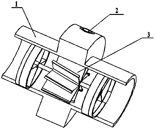
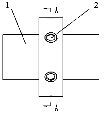
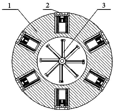
[0022] The purpose of the present invention is to provide a hydraulic piezoelectric-electromagnetic composite power generation system, which can make full use of the pressure fluctuation and impact energy of the hydraulic system to generate power, and provide internal power supply for the hydraulic system.

[0023] In order to make the above objects, features and advantages of the present invention more comprehensible, the present invention will be further desc...


PUM


Abstract

The invention relates to a hydraulic type piezoelectric-electromagnetic combined power generation system. The system is composed of an energy accumulator and a power generation device; one end of thepower generation device is communicated with the energy accumulator through a pipeline; the other end of the power generation device is communicated with an applied hydraulic system; the energy accumulator plays a role in stabilizing the pressure of the applied hydraulic system; in a pressure stabilization process, the energy accumulator is continuously filled with or discharges liquid, the powergeneration device generates power by using pressure oil flowing into or out of the energy accumulator; and the power generation device is composed of a shell, a combined power generation unit set anda turbine driving assembly, wherein the shell is of a circular-tube-shaped structure with a shaft shoulder boss, the combined power generation unit set is mounted in a radial hole in the shaft shoulder boss of the shell, and the turbine driving assembly is mounted in a flow passage of the shell. The hydraulic type piezoelectric-electromagnetic combined power generation system of the invention cannot only realize a power generation function, but also effectively stabilize the pressure fluctuation of the system and inhibit pressure impact. The hydraulic type piezoelectric-electromagnetic combined power generation system has the advantages of structure simple, size small, flexible installation, and convenience in integrated design.

Description

technical field [0001] The invention relates to a piezoelectric-electromagnetic composite power generation device, in particular to a piezoelectric-electromagnetic composite power generation system applied in a hydraulic system. Background technique [0002] With the development of hydraulic technology, more and more sensors and micro-electromechanical systems are applied to hydraulic systems. However, the traditional power supply method supplies power to external power sources. Therefore, a large number of wires have to be inserted into the system, resulting in hydraulic pressure. The power lines of the system are complicated, which increases the difficulty of system installation and maintenance, and seriously affects the system integration design. Therefore, providing an internal power supply mode of the hydraulic system is of great significance for simplifying the system and integrating the design. [0003] In hydraulic systems, pressure fluctuations and shocks are very ...

Claims


Application Information

Patent Timeline
Patent Type & Authority Applications(China)
IPC IPC(8): H02K7/18H02K35/02H02N2/18
CPCH02K7/1869H02K7/1876H02K35/02H02N2/185
Inventor 赵小龙杨皓仁陈夏非汤海龙刘琛华
Owner 赵小龙
Why Eureka
Try Eureka