
Immersion type boiling scene video monitoring device with active cooling function

An active cooling and video monitoring technology, which is applied in the field of video monitoring, can solve the problems of poor pressure bearing capacity, troublesome installation, and inconvenient movement of monitoring devices, etc., to achieve enhanced pressure resistance and sealing performance, easy installation and use, and broaden the scope of use Effect

Pending Publication Date: 2019-11-19
LANZHOU UNIVERSITY OF TECHNOLOGY
View PDF0 Cites 0 Cited by
  • Summary
  • Abstract
  • Description
  • Claims
  • Application Information

AI Technical Summary

Problems solved by technology

[0004] The technical problem to be solved by the present invention is to provide an immersion-type boiling scene video monitoring device with active cooling to solve the poor pressure bearing capacity of the existing boiling monitoring device proposed in the above-mentioned background technology. , the sealing performance of the end face is poor, and the existing visualization device can only be used to study the boiling scene of a given heat transfer situation and a given heat transfer tube. At the same time, it is necessary to set up a separate observation window, which is very troublesome to install. The tube is fixed as a whole, which is inconvenient to move the monitoring device, and it is inconvenient to observe the boiling scene under unknown working conditions in real time

Method used


Image

  • Immersion type boiling scene video monitoring device with active cooling function
  • Immersion type boiling scene video monitoring device with active cooling function
  • Immersion type boiling scene video monitoring device with active cooling function

Examples


Embodiment Construction

[0021] The following will clearly and completely describe the technical solutions in the embodiments of the present invention with reference to the accompanying drawings in the embodiments of the present invention. Obviously, the described embodiments are only some, not all, embodiments of the present invention. Based on the embodiments of the present invention, all other embodiments obtained by persons of ordinary skill in the art without making creative efforts belong to the protection scope of the present invention.

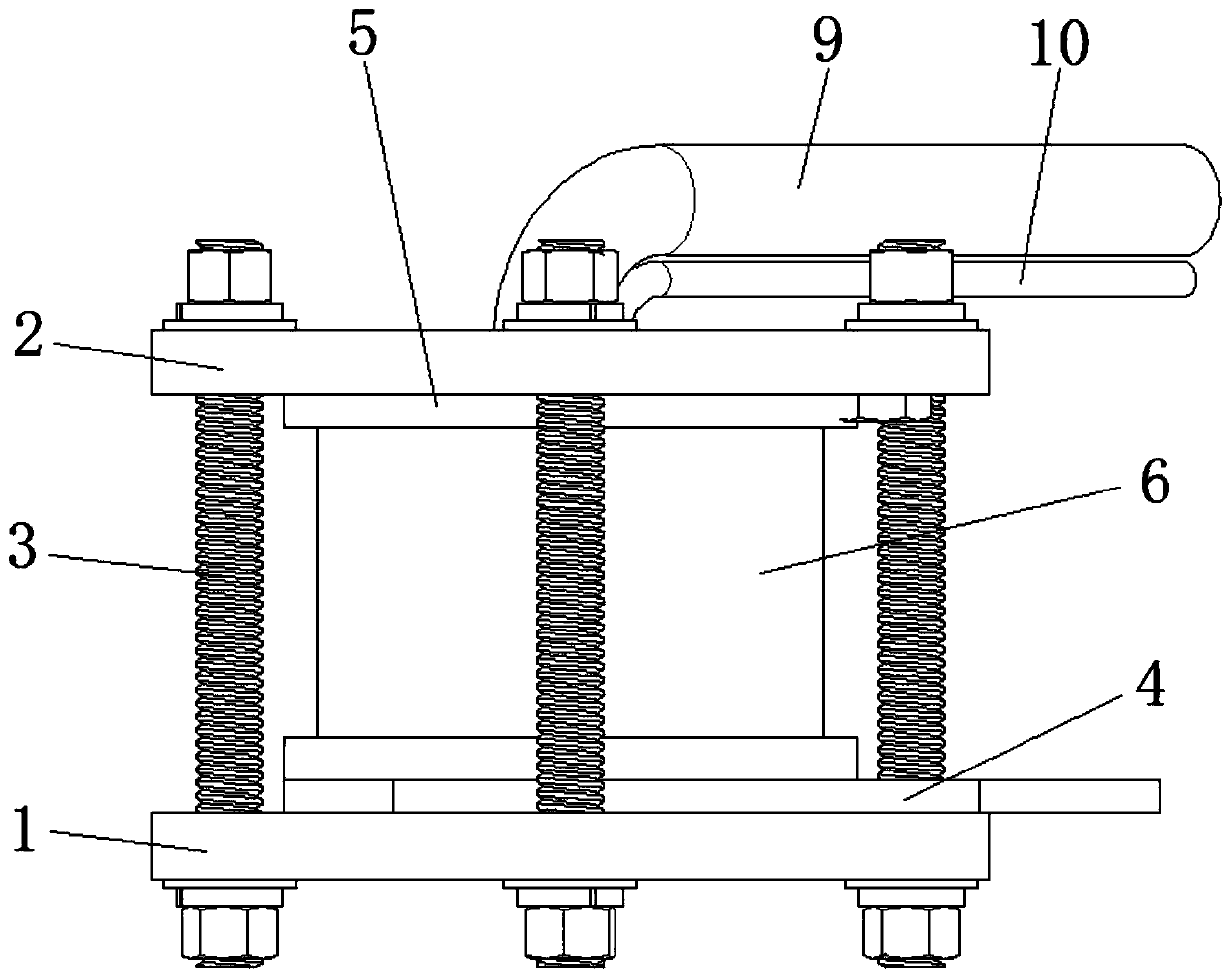
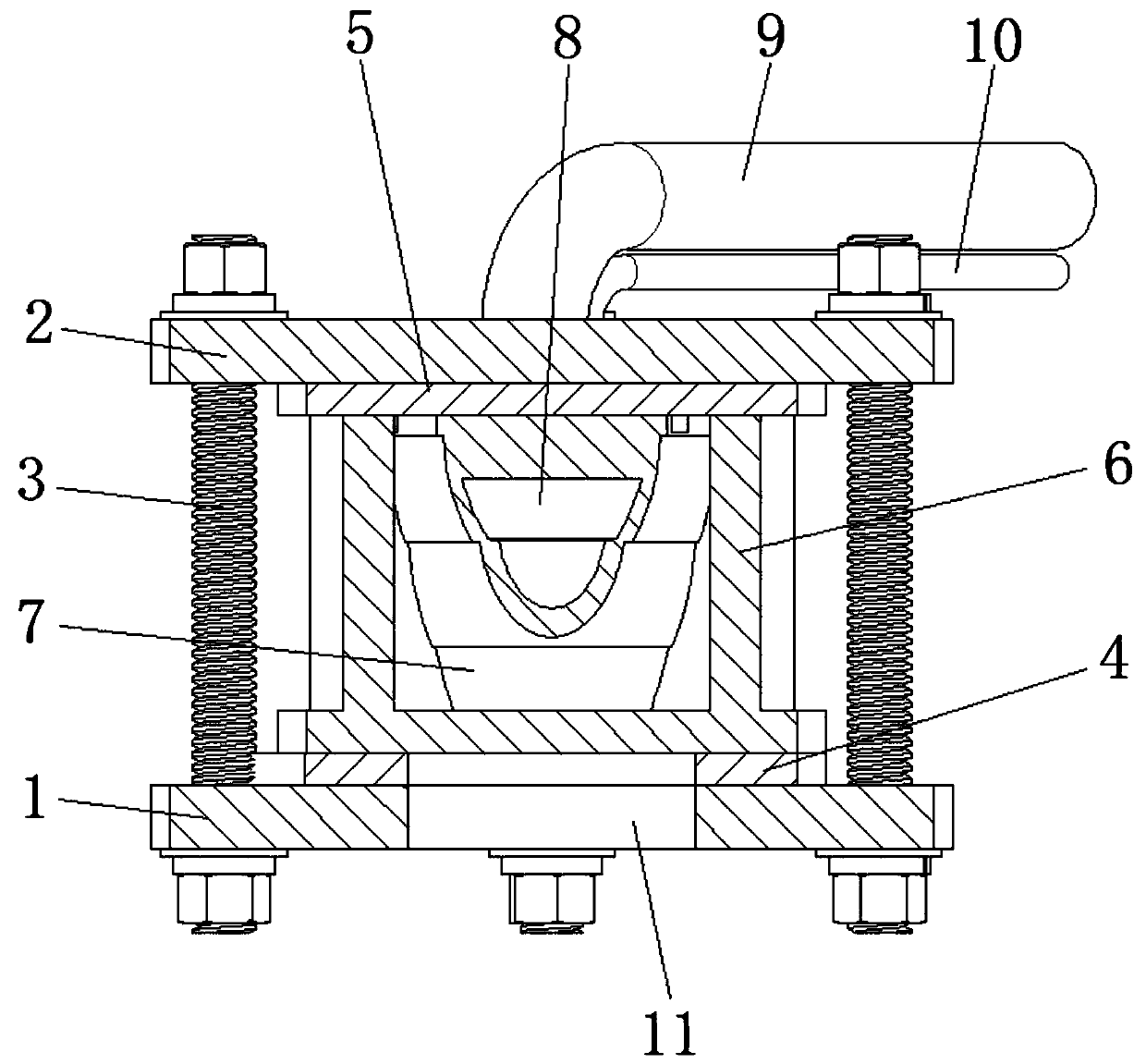
[0022] Such as Figure 1-3 As shown, the present invention provides a technical solution: an immersion-type boiling scene video monitoring device with active cooling, comprising a flange 1 with a communication hole and a flange cover 2 fixedly connected to the flange 1 through bolts 3 , the inner side of the flange 1 is provided with a first gasket 4, and the inner side of the flange cover 2 is provided with a second gasket 5, and the flange 1 is completed by ...


PUM


Abstract

The invention provides an immersion type boiling scene video monitoring device with an active cooling function. The immersion type boiling scene video monitoring device includes a flange provided witha communicating hole, and a flange cover which is fixedly connected with the flange through a bolt, wherein a glass cylinder is fixed between the flange and the flange cover; a protective shell is mounted in the glass cylinder; a communicating opening is formed in the end, facing the flange, of the protective shell; a camera is installed in the protective shell; an image collecting part of the camera faces the same direction as the communicating opening; and a cooling pipe is further installed at the side end of the protective shell, and the other end of the cooling pipe extends out of the flange, and the inner space of the protective shell communicates with the outside through the cooling pipe. The immersion type boiling scene video monitoring device solves the problems that an existingboiling monitoring device is poor in pressure bearing capacity, and the end face sealing performance is poor and the monitoring working condition is single in the prior art, and injects compressed cooling gas into the cooling pipe to absorb heat and then discharged the heat, so as to enable the camera in a protective shell to continuously and accurately monitor, and meanwhile, the whole device canmonitor boiling scenes at different positions by moving the cooling pipe.

Description

technical field [0001] The invention belongs to the technical field of video monitoring, in particular to an immersion-type boiling scene video monitoring device with active cooling. Background technique [0002] In various fields such as thermal power, nuclear power, and chemical industry, it is necessary to observe the boiling scene of liquid under high temperature and high pressure conditions, and it is also necessary to observe the boiling scene for extreme conditions such as corrosive liquids. [0003] The existing boiling monitoring device has poor pressure bearing capacity and poor sealing performance of the end face, so it cannot be used under high temperature and high pressure conditions, and the existing visualization device can only be used to study the boiling scene of a given heat transfer situation and a given heat transfer tube. At the same time, a separate observation window needs to be set up, which is extremely troublesome to install. The monitoring device ...

Claims


Application Information

Patent Timeline
Patent Type & Authority Applications(China)
IPC IPC(8): H04N7/18H04N5/225G03B17/55
CPCH04N7/183G03B17/55H04N23/51
Inventor 吴江波韦佳吟杜小泽刘姝君郭新瑞刘杰王文婷苏亚琴
Owner LANZHOU UNIVERSITY OF TECHNOLOGY
Features
  • Generate Ideas
  • Intellectual Property
  • Life Sciences
  • Materials
  • Tech Scout
  • Unparalleled Data Quality
  • Higher Quality Content
  • 60% Fewer Hallucinations
Learn More