Planetary stirring device with stirring paddle capable of vertical reciprocating motion and method

A reciprocating motion and planetary stirring technology, which is applied to mixers with rotating stirring devices, transportation and packaging, chemical instruments and methods, etc., can solve the problems of unstable stirring devices, prone to periodic vibration, and low stirring efficiency. Achieve the effect of overcoming the instability of the stirring device, avoiding uneven stirring effect, and good stirring effect

Active Publication Date: 2019-11-22
SHANDONG UNIV
View PDF3 Cites 19 Cited by
  • Summary
  • Abstract
  • Description
  • Claims
  • Application Information

AI Technical Summary

Problems solved by technology

[0002] The stirring device is one of the most common mixing devices in the industry. The existing stirring device mainly has two forms: the stirring shaft is arranged at the center of the tank body and the stirring shaft is arranged at the eccentric part of the tank body. The inventors found that when stirring When the shaft is set at the center of the tank, the internal flow field is symmetrical and the stirring effect is not good. When the stirring shaft is set at the eccentric part of the tank, the entire stirring device is unstable and prone to periodic vibrations, and because the stirring shaft Eccentric setting, the stirring effect on the eccentric side will be better and the stirring effect on the other side will be poor. The inventor also found that the current stirring paddle is fixed on the stirring shaft, along the vertical axis of the tank, There are only stirring paddles on the stirring shaft at the set position. For a tank with a relatively large length and diameter, there is still a large range of dead angles in the vertical direction of the tank that cannot be removed, resulting in different mixing effects of materials in different layers. Low

Method used


Image

  • Planetary stirring device with stirring paddle capable of vertical reciprocating motion and method
  • Planetary stirring device with stirring paddle capable of vertical reciprocating motion and method
  • Planetary stirring device with stirring paddle capable of vertical reciprocating motion and method

Examples


Embodiment 2

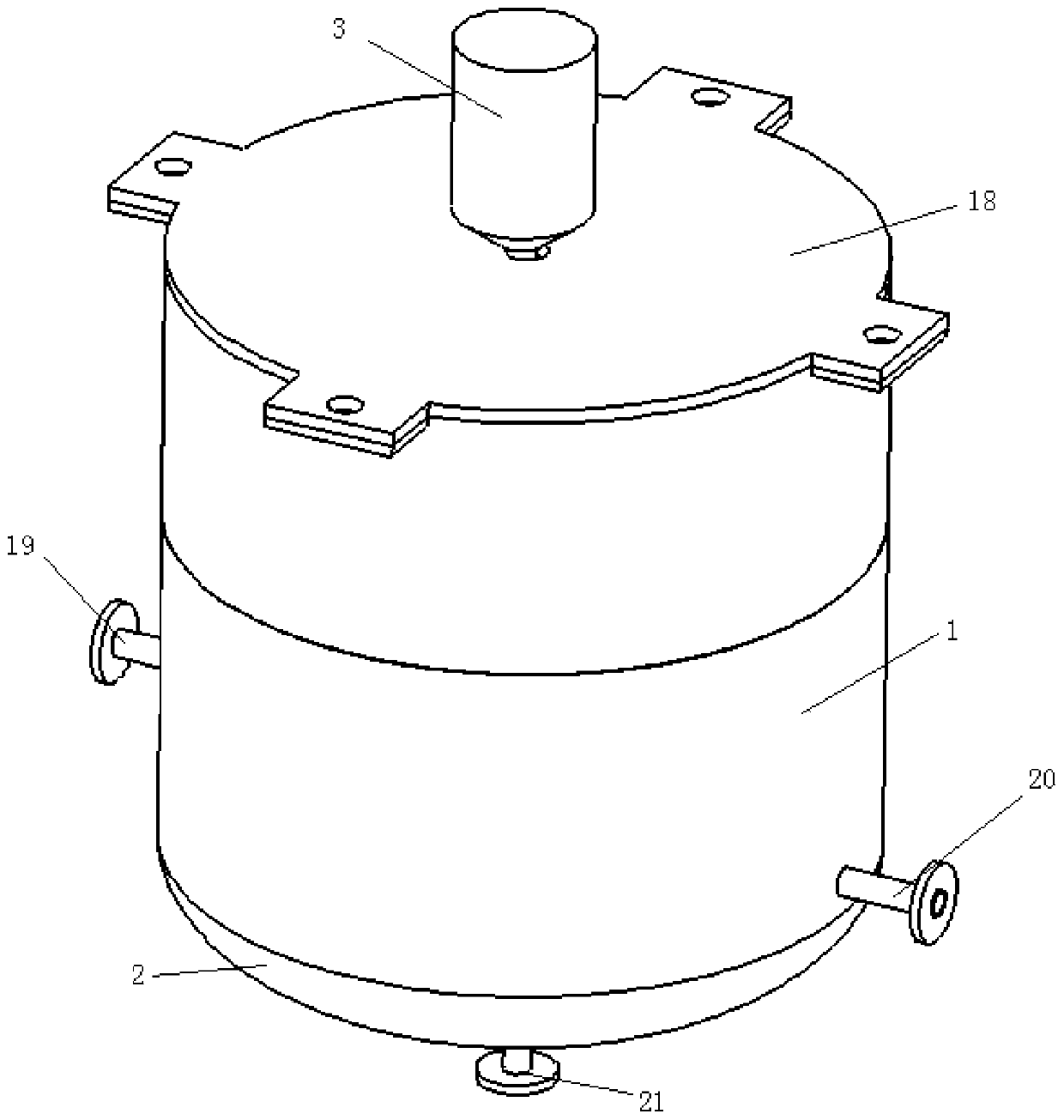
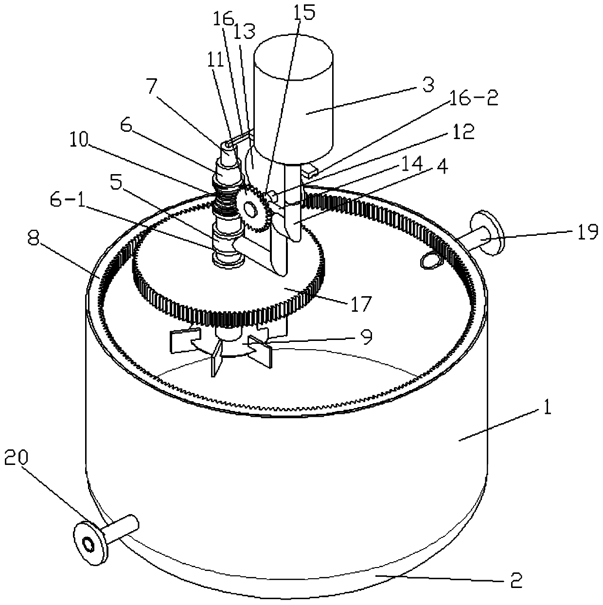
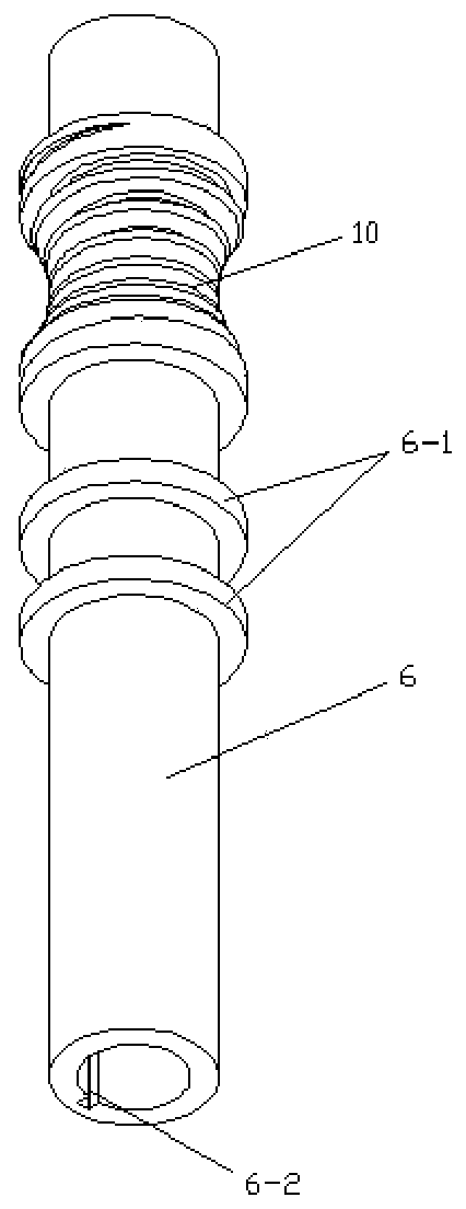
[0046] This embodiment discloses a working method of a planetary stirring device with vertical reciprocating motion of the stirring paddle: the staff injects materials into the barrel through the feeding pipe, the deceleration motor drives the rotating arm to rotate, and the stirring shaft assembly moves along the set circle. The track makes a revolution movement, and at the same time, under the meshing action of the gear and the inner ring gear, the stirring shaft assembly rotates around its own axis, the inner stirring shaft drives the stirring paddle to rotate, and the material is stirred, and the rotation of the outer stirring shaft can pass through the worm gear and the transmission shaft The cam is driven to rotate, and the cam is in contact with the top plate, which can drive the top plate to reciprocate in the vertical direction, thereby driving the inner stirring shaft and the stirring paddle to reciprocate in the vertical direction.


PUM


Abstract

The invention relates to a planetary stirring device with a stirring paddle capable of vertical reciprocating motion and a method. The device comprises a driving mechanism positioned above a cylinderbody, wherein the driving mechanism is connected with a rotating arm; the end part of the rotating arm is connected with a stirring shaft assembly capable of rotating around the axis of the stirring shaft assembly; the axis of the stirring shaft assembly deviates from the axis of the cylinder body; the stirring shaft assembly comprises an outer stirring shaft and an inner stirring shaft which arecoaxially arranged; the outer stirring shaft sleeves the inner stirring shaft; the outer stirring shaft is connected with a gear; the gear is meshed with an inner gear ring fixed on the cylinder body;the outer stirring shaft can drive the inner stirring shaft to rotate around the axis of the inner stirring shaft; the inner stirring shaft can also move along the axis direction of the inner stirring shaft; the outer stirring shaft is connected with a cam through a transmission mechanism; the cam makes contact with a top plate; the top plate is connected with the inner stirring shaft; the cam can drive the inner stirring shaft to move in the axis direction of the stirring shaft assembly through the top plate; the stirring paddle is fixed to the inner stirring shaft. The stirring device is good in stirring effect.

Description

technical field [0001] The invention relates to the technical field of stirring devices, in particular to a planetary stirring device and method with vertical reciprocating paddles. Background technique [0002] The stirring device is one of the most common mixing devices in the industry. The existing stirring device mainly has two forms: the stirring shaft is arranged at the center of the tank body and the stirring shaft is arranged at the eccentric part of the tank body. The inventors found that when stirring When the shaft is set at the center of the tank, the internal flow field is symmetrical and the stirring effect is not good. When the stirring shaft is set at the eccentric part of the tank, the entire stirring device is unstable and prone to periodic vibrations, and because the stirring shaft Eccentric setting, the stirring effect on the eccentric side will be better and the stirring effect on the other side will be poor. The inventor also found that the current stir...

Claims


Application Information

Patent Timeline
Patent Type & Authority Applications(China)
IPC IPC(8): B01F7/16B01F7/18B01F7/30B01F11/00
CPCB01F27/806B01F27/951B01F27/95B01F31/40B01F27/90
Inventor 孙海耀张翠勋杨锋苓
Owner SHANDONG UNIV
Why Eureka
Try Eureka