
A centrifugal microfluidic chip reagent packaging structure

A microfluidic chip and packaging structure technology, applied in the field of medical machinery, can solve problems such as low installation stability, complex sealing structure, and difficult installation, and achieve the effects of reducing resource waste, compact sealing structure, and high installation stability

Active Publication Date: 2021-03-19
BEIJING 3S CENTURY TECH CORP
View PDF1 Cites 0 Cited by
  • Summary
  • Abstract
  • Description
  • Claims
  • Application Information

AI Technical Summary

Problems solved by technology

[0004] The microfluidic chip packaging structure in the above-mentioned patents has the following problems. The plugs need to be installed on the reagent outlets one by one. The installation is difficult and the installation stability is low. The entire sealing structure is relatively complicated, inconvenient to use, and cannot be recycled. Resources Large amount of waste

Method used


Image

  • A centrifugal microfluidic chip reagent packaging structure
  • A centrifugal microfluidic chip reagent packaging structure
  • A centrifugal microfluidic chip reagent packaging structure

Examples


Embodiment Construction

[0022] Next, the technical solutions in the embodiments of the present invention will be apparent from the embodiment of the present invention, and it is clearly described, and it is understood that the described embodiments are merely embodiments of the present invention, not all of the embodiments. Based on the embodiments in the present invention, those of ordinary skill in the art will belong to the scope of the present invention in the scope of the present invention without any other embodiments obtained without creative labor.

[0023] In the description of the invention, it is to be understood that the terms "opening", "upper", "lower", "thickness", "top", "medium", "within", "around", etc. Indicates the orientation or positional relationship, is merely described in order to facilitate the description of the present invention, rather than indicating or implying that the components or elements must have a specific orientation, and therefore cannot be understood as limiting t...


PUM


Abstract

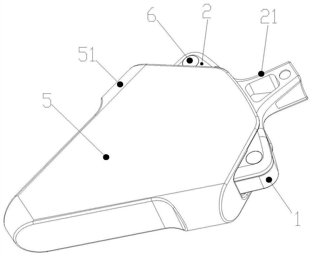
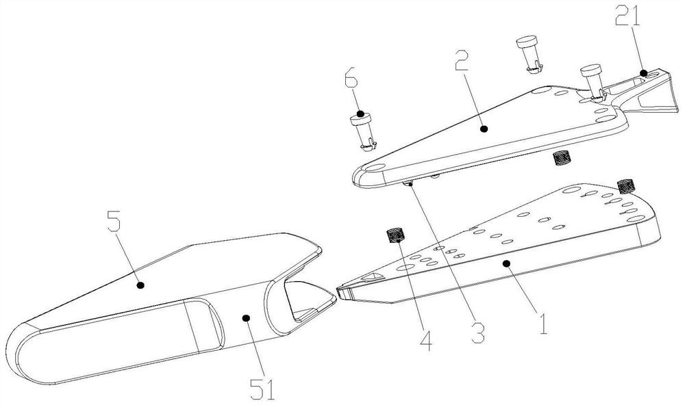
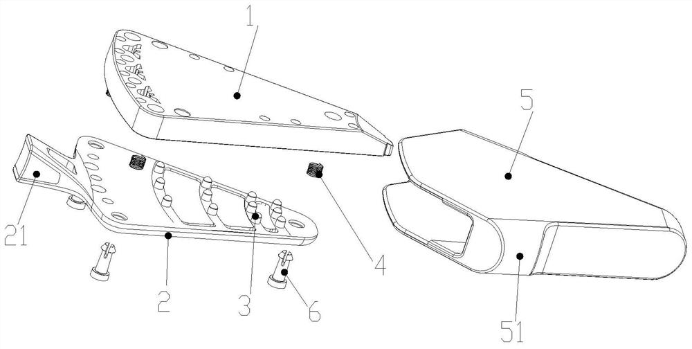
The invention discloses a centrifugal microfluidic chip reagent packaging structure, which comprises a packaging cavity; a cover plate movably assembled at the upper end of the packaging cavity, wherein a plurality of plugging blocks are arranged on the cover plate, and the plugging blocks are in one-to-one correspondence with reagent outlets of the packaging cavity; an elastic piece which is arranged between the cover plate and the packaging cavity; and a shell which is arranged on the cover plate and the packaging cavity in a sleeving manner. The plugging blocks are integrally formed on thecover plate; wherein the cover plate and the packaging cavity move relative to each other, so that the plugging blocks on the cover plate can close or open the reagent outlets of the packaging cavity.The plugging blocks do not need to be installed on the reagent outlets one by one, installation is easy and convenient, installation stability is high, the whole sealing structure is compact, use isconvenient, cyclic utilization can be achieved, and resource waste is reduced.

Description

Technical field [0001] The present invention relates to the field of medical machinery, and is specifically a centrifugal microfluidic chip reagent package structure. Background technique [0002] The microfluidic chip is a hot spot in the development of the current miniature analysis system. The microfluidic chip integrates the sample detection of biological, chemical, medical and other analytical processes to a small chip. The microfluidic chip has the controllable, consumption sample and very small consumption, analysis speed, etc., which can be analyzed by 100 samples in a few minutes or less time, and can achieve the sample online Processing and analysis of the whole process. [0003] However, the fluid package structure of the microfluidic chip has always been a problem that is from the unparticles of the field. Including: encapsulated cavities, pliers, cover and casing formed of microfluidic chip, the casing abuts the upper surface of the plug body to generate a variable p...

Claims


Application Information

Patent Timeline
Patent Type & Authority Patents(China)
IPC IPC(8): B01L3/00
CPCB01L3/5027B01L3/502707B01L3/50273B01L2200/0689B01L2200/10B01L2200/16B01L2300/08B01L2400/0409
Inventor 彭悦蕾冯尧
Owner BEIJING 3S CENTURY TECH CORP
Learn More