Mud discharging pipe structure of dredger

A technology of a mud discharge pipe and a dredger, which is applied in the field of machinery and can solve the problems of not being able to adjust the direction of the mud discharge pipe according to the demand, and inconvenient to clean the mud discharge pipe.

Active Publication Date: 2016-10-12
ZHEJIANG OCEAN UNIV
View PDF6 Cites 5 Cited by
  • Summary
  • Abstract
  • Description
  • Claims
  • Application Information

AI Technical Summary

Problems solved by technology

However, according to needs, the existing mud discharge pipe cannot adjust the direction of the mud discharge pipe or make it bend according to the demand during use. In addition, when the mud discharge pipe is blocked during use, it is also inconvenient to clean the mud discharge pipe.

Method used


Image

  • Mud discharging pipe structure of dredger
  • Mud discharging pipe structure of dredger
  • Mud discharging pipe structure of dredger

Examples


Embodiment Construction

[0033] The following are specific embodiments of the present invention and in conjunction with the accompanying drawings, the technical solutions of the present invention are further described, but the present invention is not limited to these embodiments.

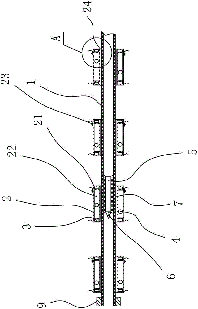
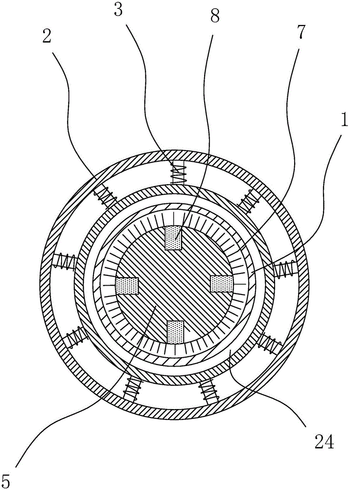
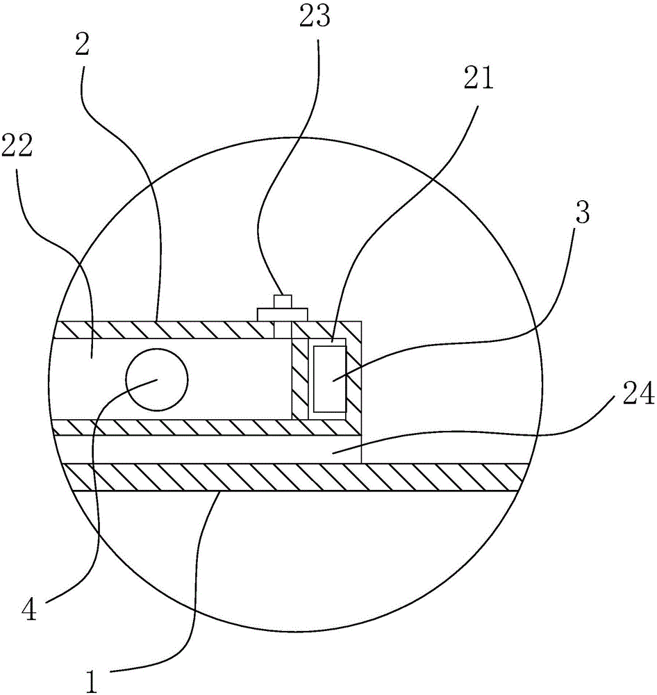
[0034] Such as Figure 1-3 As shown, the dredging pipe structure of the dredger includes a pipe body 1, and several buoyant floating bodies 2 are sleeved on the pipe body 1 along the axial direction, and the floating bodies 2 and the pipe body 1 are in clearance fit. 1. It is made of non-ferromagnetic materials such as plastic, nylon or colloid. There is a cavity inside the floating body 2, and an electromagnet 3 is arranged in the cavity. The electromagnet 3 is located at both ends of the floating body 2 and at the free end of the tube body 1. Also set limit block 9.

[0035] Specifically, the floating body 2 is cylindrical, and the axial direction of the floating body 2 is provided with a through hole 24 with a circular...


PUM


Abstract

The invention provides a mud discharging pipe structure of a dredger and belongs to the technical field of machines. The mud discharging pipe structure of the dredger comprises a pipe body. The pipe body is sleeved with multiple floating bodies having buoyancy in the axial direction. The floating bodies and the pipe body are in clearance fit. The pipe body is made of a non-magnetic material. A cavity is formed in each floating body. Electromagnets are arranged in each cavity and located at the two ends of the corresponding floating body. A limiting block is further arranged at the free end of the pipe body. By means of the mud discharging pipe structure of the dredger, in the use process, the electromagnets on the floating bodies are controlled so that the polarities of the adjacent floating bodies can be opposite and can be mutually attracted, and therefore the multiple floating bodies can be gathered together to increase the buoyancy or gravity of the pipe body at the position to meet work requirements; and the polarities can also be the same so that the floating bodies can get away from one another, the buoyancy loaded on the pipe body is scattered, and the purpose of adjusting the walking direction of a mud discharging pipe or bending the mud discharging pipe can be achieved.

Description

technical field [0001] The invention belongs to the technical field of machinery and relates to a dredging pipe structure of a dredger. Background technique [0002] The task of the dredger is to carry out underwater earthwork construction, specifically: digging, widening and cleaning existing channels and ports; excavating new channels, ports and canals; dredging piers, docks, locks and other water It is a sharp tool for blowing sand and reclamation, such as the foundation trench of industrial buildings and throwing the excavated sand into the deep sea or dredging and filling in land depressions to make fields. [0003] The cutter suction dredger extends the suction pipe to the surface of the underwater mud layer from the side or stern of the ship, and starts the suction pump in the cabin to suck, transport, load and unload the river bottom sediment to the transport ship or directly to the shore; Due to the deposition and compaction of the river bottom sediment layer, it i...

Claims


Application Information

Patent Timeline
Patent Type & Authority Applications(China)
IPC IPC(8): E02F3/88E02F3/90E02F5/28
CPCE02F3/885E02F3/90E02F5/28
Inventor 张玉莲章海
Owner ZHEJIANG OCEAN UNIV
Why Eureka
Try Eureka