
Ultraviolet light sterilization robot

An ultraviolet light and robot technology, applied in the directions of manipulators, control devices, vehicle parts, etc., can solve the problems that robots cannot recognize, cannot be sterilized, and cannot save working power, etc., and achieve the effect of saving working power.

Active Publication Date: 2019-11-22
佛山紫熙慧众科技有限公司
View PDF8 Cites 2 Cited by
  • Summary
  • Abstract
  • Description
  • Claims
  • Application Information

AI Technical Summary

Problems solved by technology

The specific disinfection method is to install an ultraviolet light emitting device on the roof or ceiling when there is no one in the room, and use ultraviolet light to fully disinfect the room. This method can effectively remove bacteria on the desktop, bed surface and ground, but The bottom of the table, the bottom of the hospital bed, and the part of the ground covered by the bed or the table cannot be radiated by ultraviolet light at all, so that the surface of the above objects cannot be disinfected and sterilized. Now there are household products that can simultaneously sterilize the bottom of the furniture and the ground. However, it is not necessary to use disinfection and sterilization robots to repeatedly sterilize the ground exposed to ultraviolet radiation in the hospital ward. Although the robot in the prior art can sterilize the surface of the object, the robot cannot recognize the location at that time Whether ultraviolet sterilization is required, that is, the robot cannot identify whether it is under each piece of furniture or whether the ground is covered by furniture. On the other hand, the working environment of a household sterilization robot does not have an ultraviolet light emitting device at a high place in the house. Therefore, In the prior art, when the robot is walking, the ultraviolet sterilizing device is always in the working state, so as to sterilize and remove impurities in the whole house, and the robot cannot realize the function of saving working power

Method used


Image

  • Ultraviolet light sterilization robot
  • Ultraviolet light sterilization robot
  • Ultraviolet light sterilization robot

Examples


Embodiment Construction

[0022] Embodiments of the present invention are described in detail below, examples of which are shown in the drawings, wherein the same or similar reference numerals denote the same or similar elements or elements having the same or similar functions throughout. The embodiments described below by referring to the figures are exemplary only for explaining the present invention and should not be construed as limiting the present invention.

[0023]In describing the present invention, it should be understood that the terms "center", "longitudinal", "transverse", "length", "width", "thickness", "upper", "lower", "front", " Orientation indicated by rear, left, right, vertical, horizontal, top, bottom, inside, outside, clockwise, counterclockwise, etc. The positional relationship is based on the orientation or positional relationship shown in the drawings, which is only for the convenience of describing the present invention and simplifying the description, rather than indicating o...


PUM


Abstract

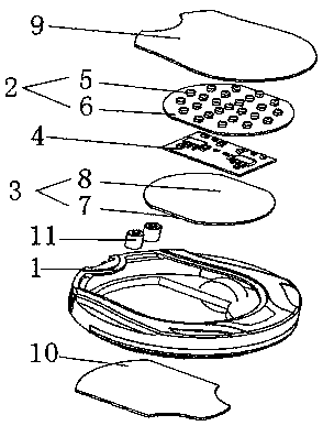
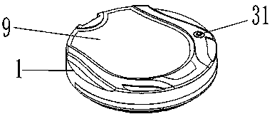
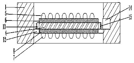
The invention provides an ultraviolet light sterilization robot which comprises a self-walking robot body and a control assembly arranged on the self-walking robot body. An ultraviolet light sterilization assembly is arranged in the self-walking robot body. The self-walking robot body and the ultraviolet sterilization assembly are electrically connected with the control assembly. The ultraviolet sterilization assembly transmits ultraviolet light to be used for conducting sterilization and disinfection work on the surfaces of objects above and / or below the self-walking robot body. A distance measuring device is arranged on the top of the self-walking robot body and is used for obtaining the perpendicular height value between the upper surface of the self-walking robot body and the surfacesof the objects above the self-walking robot body and sending the perpendicular height value to the control assembly. The control assembly controls the ultraviolet light sterilization assembly to be turned on and turned off according to the perpendicular height value, and the technical effect of saving the work electric quantity of the robot body is achieved.

Description

technical field [0001] The invention relates to the technical field of ultraviolet light disinfection, in particular to an ultraviolet light sterilization robot. Background technique [0002] In hospital buildings, each ward or medical room needs to be disinfected with ultraviolet light to eliminate indoor bacteria and germs. The specific disinfection method is to install an ultraviolet light emitting device on the roof or ceiling when there is no one in the room, and use ultraviolet light to fully disinfect the room. This method can effectively remove bacteria on the desktop, bed surface and ground, but The bottom of the table, the bottom of the hospital bed, and the part of the ground covered by the bed or the table cannot be radiated by ultraviolet light at all, so that the surface of the above objects cannot be disinfected and sterilized. Now there are household products that can simultaneously sterilize the bottom of the furniture and the ground. However, it is not nec...

Claims


Application Information

Patent Timeline
IPC IPC(8): B25J11/00B25J5/00A61L2/10B60K17/34
CPCB25J11/00B25J5/007A61L2/10B60K17/34
Inventor 周启航吴志波
Owner 佛山紫熙慧众科技有限公司
Learn More