Ejecting type jig for grabbing workpiece

A technology of taking workpieces and ejecting them is applied in the field of ejector-retracting workpiece jigs, which can solve the problems of inaccurate ejection position, workpiece damage, affecting workpiece quality, etc., and achieve the effect of stable workpiece removal process and guaranteed workpiece quality.

Pending Publication Date: 2019-11-22
SUZHOU CM TECH CO LTD
View PDF0 Cites 0 Cited by
  • Summary
  • Abstract
  • Description
  • Claims
  • Application Information

AI Technical Summary

Problems solved by technology

Using this method to take the workpiece may cause damage to the workpiece and affect the quality of the workpiece due to the inaccurate ejection position and the extrusion of the mold ejector pin and fixture on the workpiece.

Method used


Image

  • Ejecting type jig for grabbing workpiece
  • Ejecting type jig for grabbing workpiece
  • Ejecting type jig for grabbing workpiece

Examples


Embodiment Construction

[0025] Exemplary embodiments of the present disclosure will be described in more detail below with reference to the accompanying drawings. Although exemplary embodiments of the present disclosure are shown in the drawings, it should be understood that the present disclosure may be embodied in various forms and should not be limited by the embodiments set forth herein. Rather, these embodiments are provided for more thorough understanding of the present disclosure and to fully convey the scope of the present disclosure to those skilled in the art.

[0026] It should be noted that the technical features in the embodiments and optional embodiments of the present invention may be combined with each other on the premise of no conflict.

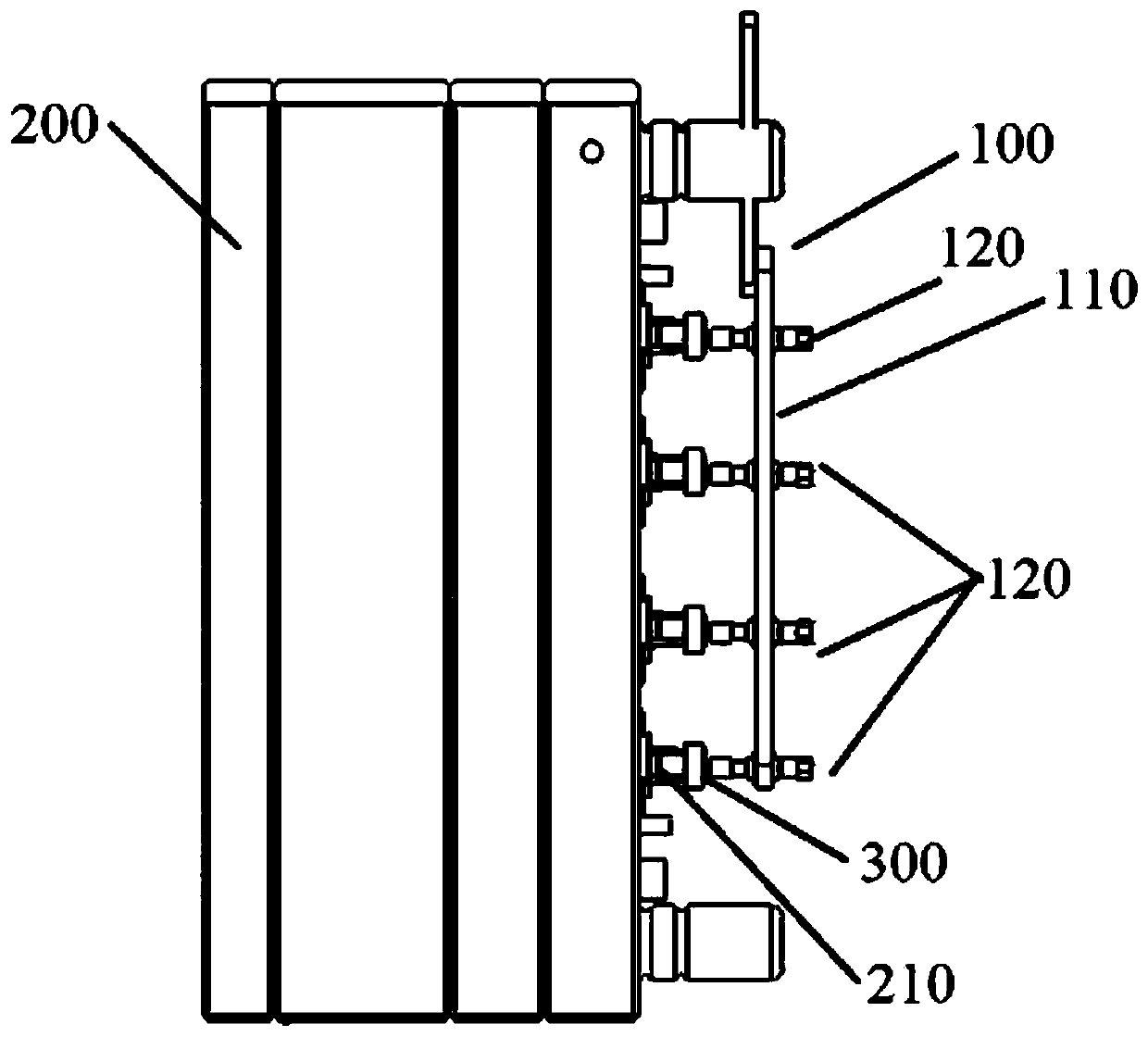
[0027] figure 1 It shows a schematic structural view of the workpiece fixture in the prior art, as figure 1 As shown, the fixture 100 for picking workpieces in the prior art includes a fixture plate 110 and a plurality of suction needles 120 arra...


PUM


Abstract

The invention provides an ejecting type jig for grabbing workpiece. The ejecting type jig is used for grabbing the workpiece on a mold and drives the workpiece to move away from the mold under the thrust action of a plurality of pushing ejector pins of the mold in the process of ejecting the workpiece by the separated ejector pins of the mold. The jig comprises a jig plate and an ejecting mechanism, wherein a plurality of through holes are formed in the jig plate; the jig plate is arranged on a fixing mechanism; the ejecting mechanism comprises a ejecting plate, a plurality of connecting shafts and a plurality of springs; one ends of the connecting shafts are fixedly connected with one side face of the ejecting plate respectively; the other ends of the connecting shafts penetrate through the through holes in the jig plate respectively; the connecting shafts are sleeved with the springs; the two ends of each spring abut against the jig plate and the ejecting plate respectively in a loosening state; and the other side face of the ejecting plate corresponds to one face provided with the pushing ejector pins on the mold. According to the technical scheme, the ejecting plate grabs the workpiece at the beginning and then compresses the springs to drive the workpiece to move together, so that the damage to the workpiece due to the change of the relative position between the ejecting plate and the workpiece is reduced.

Description

technical field [0001] The invention relates to an auxiliary equipment of an injection mold, in particular to a top-retraction type jig for taking workpieces. Background technique [0002] At present, many electronic equipment casings often use the processing method of metal parts mold injection molding in the production. When this process is processed, it is usually realized with a manipulator. The end of the manipulator is fixedly connected to suck the workpiece. Suction jig, one side of the connection part of the suction jig and the end of the manipulator are firmly connected to each other, and the jig is also equipped with a suction needle for sucking the workpiece. Usually, during the suction work, the manipulator drives the jig The jig stays at the position where the ejector pin of the mold ejects the workpiece, and the suction needle of the jig absorbs the surface of the workpiece. After the suction is firm, the manipulator moves to the position where the workpiece is...

Claims


Application Information

Patent Timeline
IPC IPC(8): B29C45/42B29C45/40B29L31/34
CPCB29C45/42B29C45/4005B29L2031/34
Inventor 陈韬
Owner SUZHOU CM TECH CO LTD
Why Eureka
Try Eureka