Embedded rail transit transportation system

A technology for rail transit and transportation systems, which is applied in the direction of railway car body components and can solve problems such as the impact of performance indicators

Pending Publication Date: 2019-11-22
深圳空铁科技股份有限公司
View PDF0 Cites 0 Cited by
  • Summary
  • Abstract
  • Description
  • Claims
  • Application Information

AI Technical Summary

Problems solved by technology

[0003] It is a very complicated problem to further optimize the rail transportation system on the basis of the existing design, and the

Method used


Image

  • Embedded rail transit transportation system
  • Embedded rail transit transportation system
  • Embedded rail transit transportation system

Examples


Embodiment Construction

[0033] The solution will be described below in conjunction with the drawings and specific implementations.

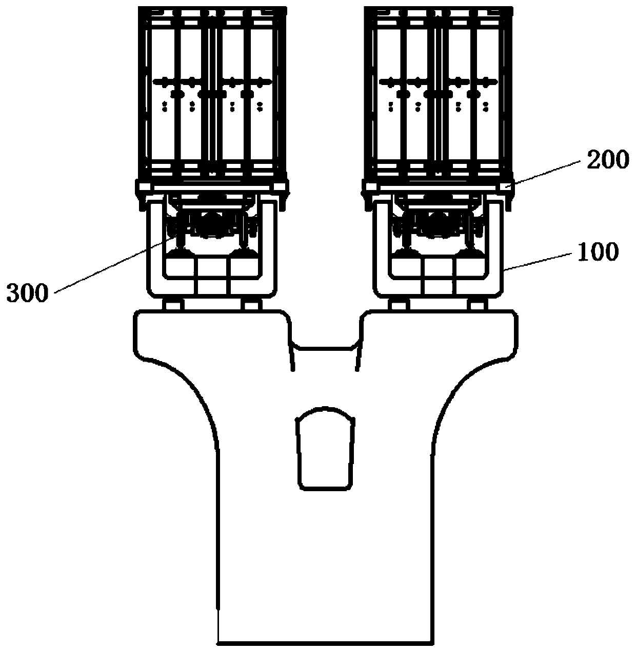
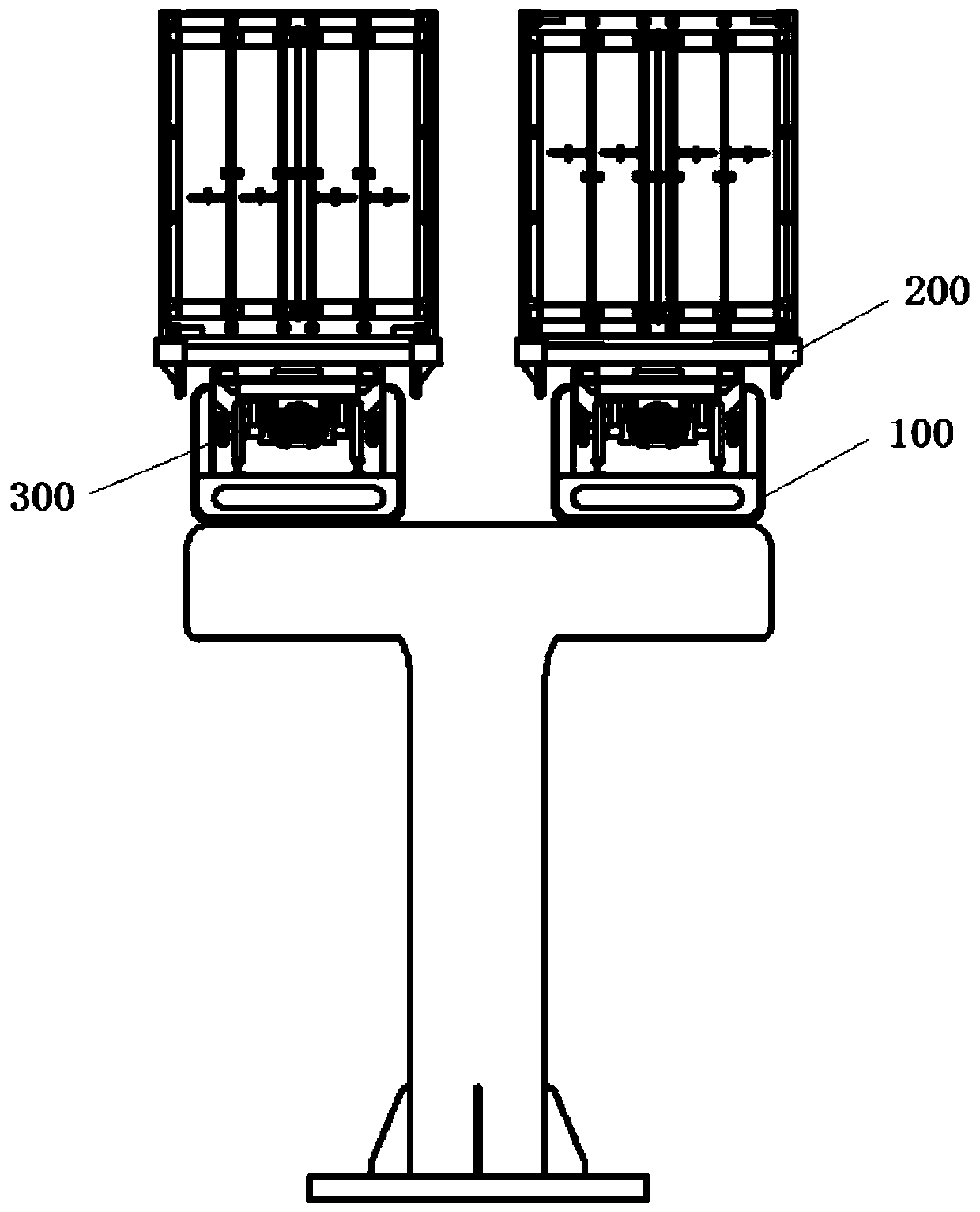
[0034] In current rail transit systems, such as subways and light rail systems, the outer edge width of the car body is usually smaller than the outer edge width of its load-bearing track. Under such an arrangement, the outer edge width of the power unit is generally larger than the outer edge width of the vehicle body, that is, the load-bearing unit, and the noise expansion is more obvious.

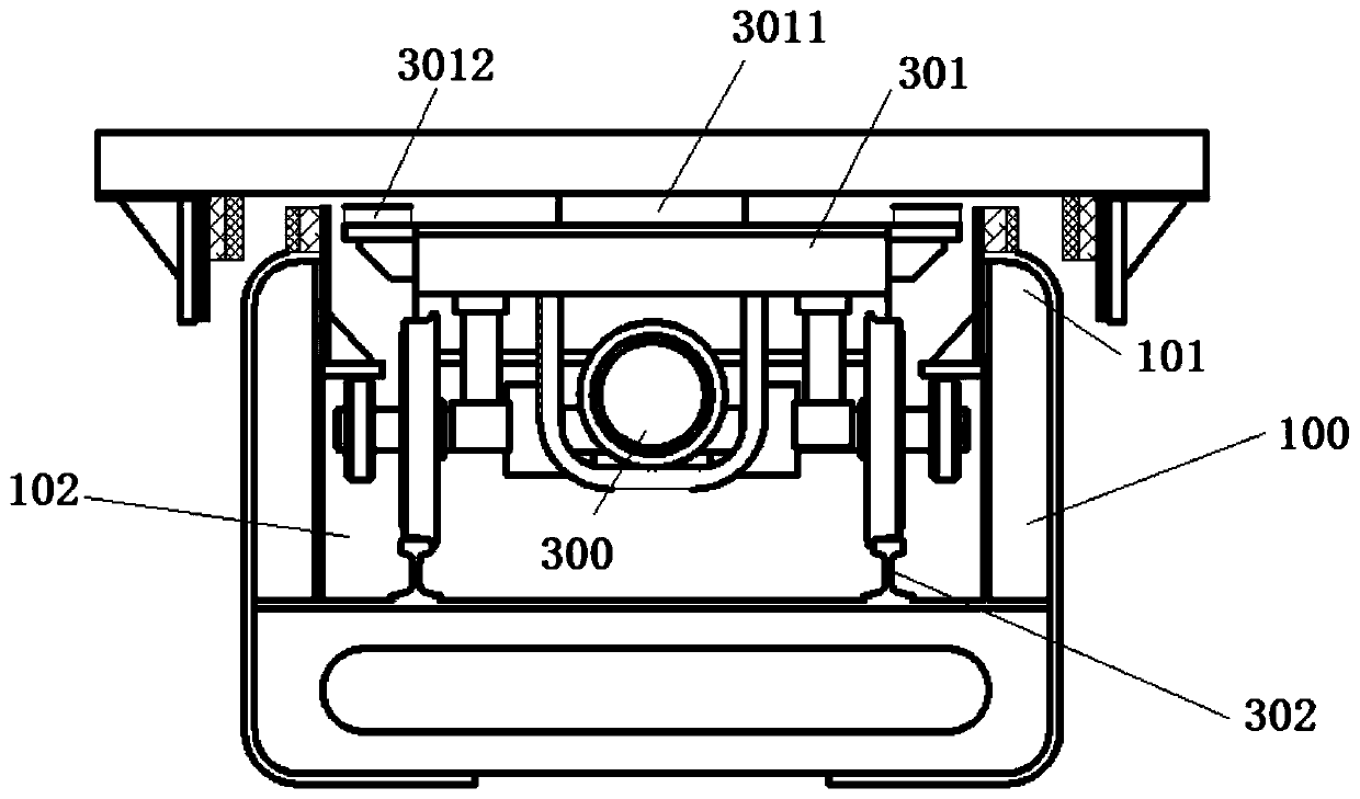
[0035] The present application improves the overall system structure to obtain an embedded rail transit system with reduced center of gravity and reduced noise. The overall design of the embedded rail transit system used is as follows:

[0036] An embedded rail transportation system includes a rail unit, a power unit, and a carrier unit; the rail unit includes a rail beam, a running channel is provided inside the rail beam, and a continuous running is provided on the upper edge of the r...


PUM


Abstract

The invention relates to the field of rail transit transportation, in particular to an embedded rail transit transportation system, which utilizes specific design between a rail beam and a supportingdevice for supporting a carrier unit to obtain the embedded rail transit transportation system with reduced gravity center, lower rail beam and bullet train duty height and reduced noise.

Description

Technical field [0001] This application relates to the field of rail transportation, in particular to an embedded rail transportation system. Background technique [0002] The current rail transit system usually includes subway systems, light rail systems, and monorail systems; most of the subway systems and light rail systems use sleepers and rails to match to form a running system; among them, the monorail system uses track beams to form a running system to support the EMU. Or the track beam and the steel rail are matched to form a running system to support the EMU. Regardless of the system structure, the current track system still has room for adjustment in terms of noise. Summary of the invention [0003] It is a very complicated problem to further optimize the rail transit system on the basis of the existing design. The optimization of one aspect of the performance index will often have a complex impact on the other aspects of the performance index. Moreover, the relevance ...

Claims


Application Information

Patent Timeline
IPC IPC(8): B61B13/00
CPCB61B13/00
Inventor 曾鉴邓茂涛何磊
Owner 深圳空铁科技股份有限公司
Why Eureka
Try Eureka