Self-adaptive variable-posture bionic mechanical foot

A bionic machine and attitude changing technology, applied in the field of engineering bionics, can solve the problem of not considering the adjustment of motion attitude in detail, and achieve the effects of improving traction performance, reducing intrusion resistance, and changing the ground contact area.

Active Publication Date: 2019-11-22
JILIN UNIV
View PDF9 Cites 4 Cited by
  • Summary
  • Abstract
  • Description
  • Claims
  • Application Information

AI Technical Summary

Problems solved by technology

[0006] A Chinese invention patent of a bionic tendon-bone synergistic rigid-flexible coupling mechanical foot for crossing the sand (application number: 201810786878.0) separates the phalanges of the main toe and the auxiliary toe, emphasizing the push-off function of the mechanical foot, through the servo motor push rod, cushioning and reducing The separation and closing of the two toes is achieved through the cooperation of the vibration mechanism and the flexible passive control mechanism. There is no detailed consideration of the different extensor / flexor tendons driving the toe extension / flexion movements of different phalanges and the movement posture of the toes in different contact periods. Adjustment, and need servo motor assistance, not completely passive

Method used


Image

  • Self-adaptive variable-posture bionic mechanical foot
  • Self-adaptive variable-posture bionic mechanical foot
  • Self-adaptive variable-posture bionic mechanical foot

Examples


Embodiment Construction

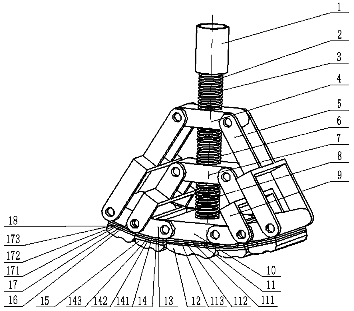
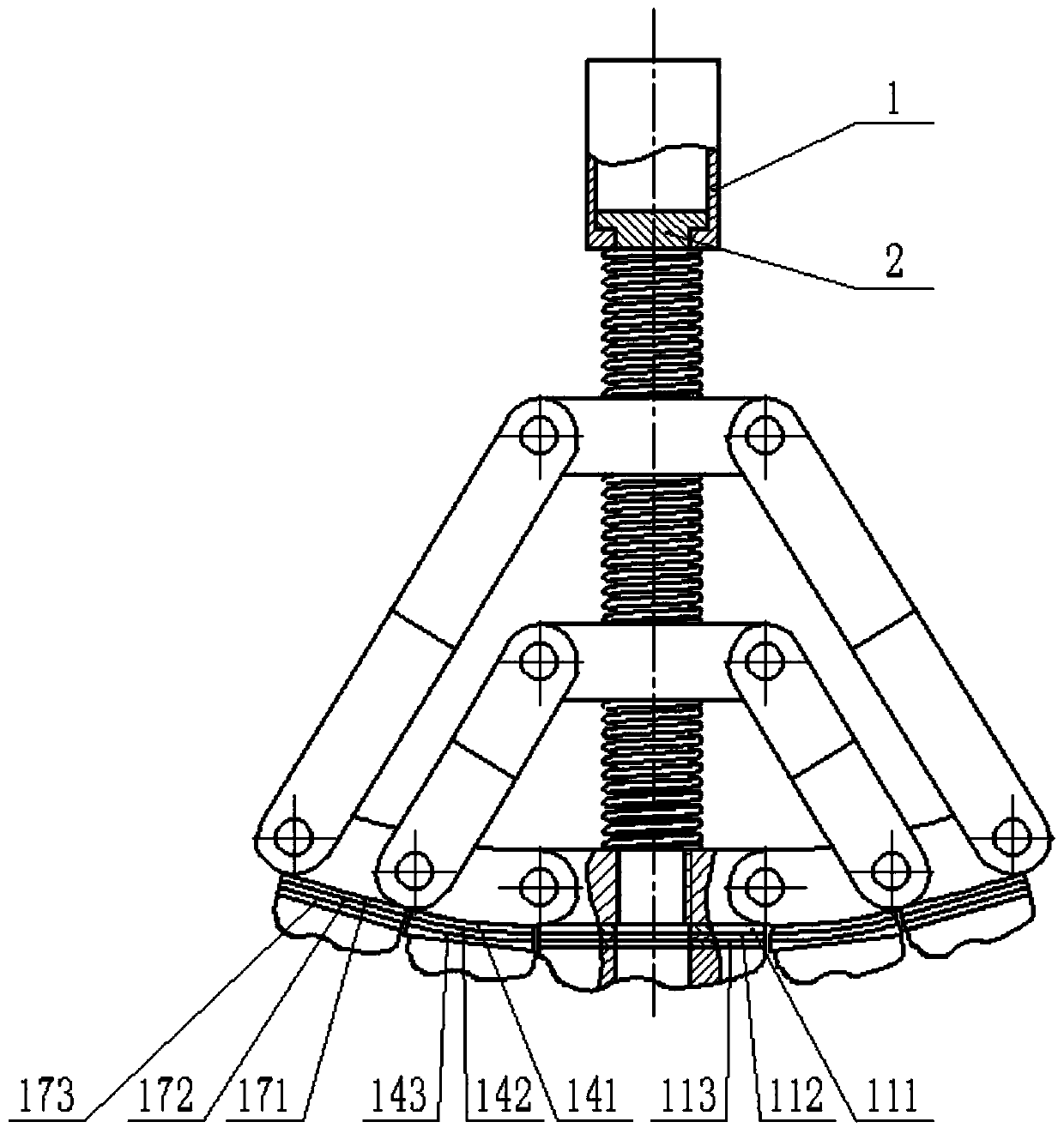
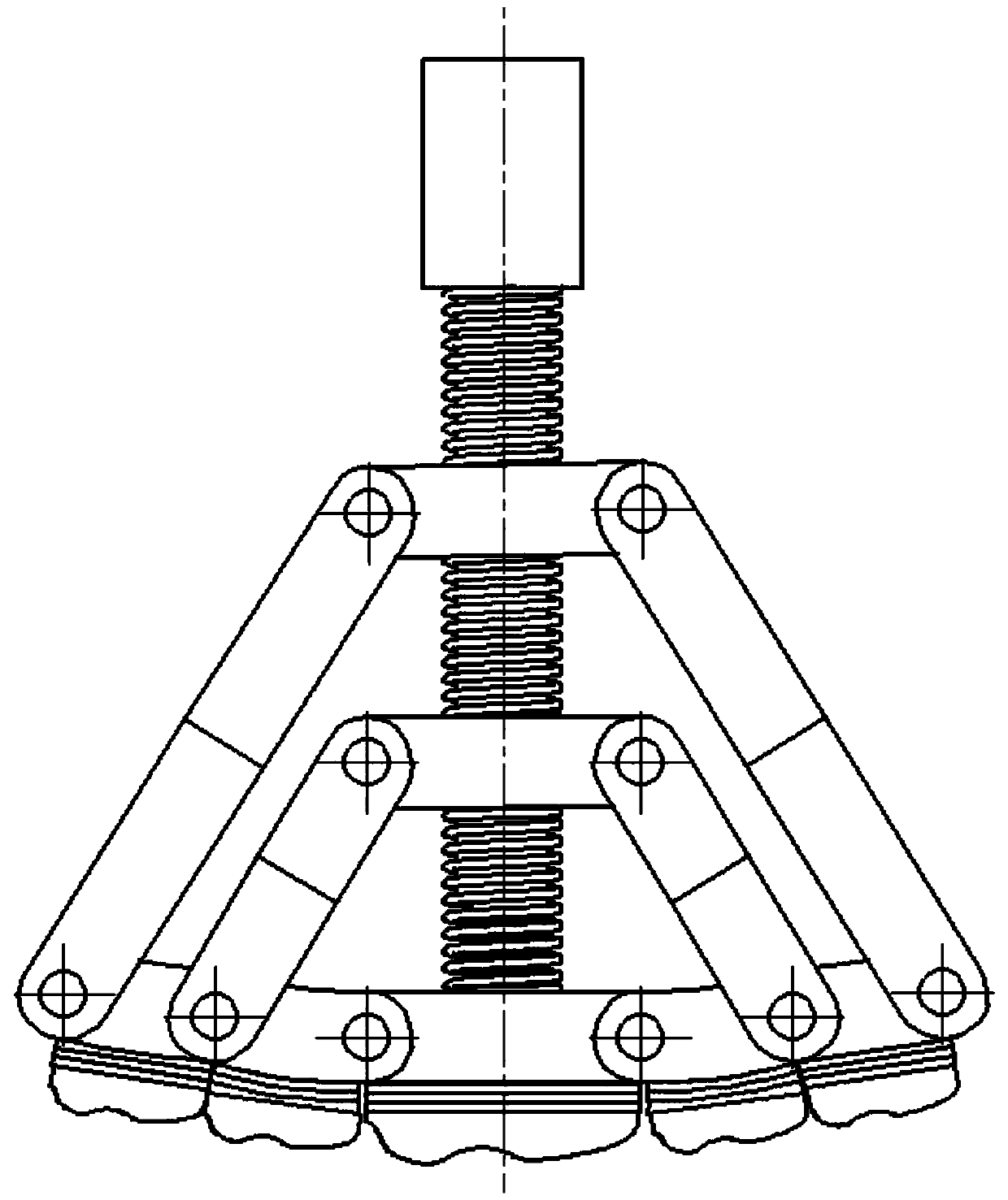
[0024] The following combination Figure 1 to Figure 6 , the specific implementation of the bionic mechanical foot will be described.

[0025] An adaptive posture-changing bionic mechanical foot, comprising a load-bearing rod 1, a guide rod 2, a first slider linkage mechanism, a second slider linkage mechanism, a first toe mechanism, a pair of second toe mechanisms, a on the third toe body. After the guide rod 2 passes through the load-bearing rod 1, the first slider 4 of the first slider linkage mechanism, and the second slider 7 of the second slider linkage mechanism, it is threadedly connected with the first toe mechanism; The second toe mechanism is respectively hinged on the left and right sides of the first toe mechanism; a pair of third toe mechanisms are respectively hinged on the outside of the second toe mechanism on the corresponding side. The ends of the two first connecting rods 5 of the first slider link mechanism are respectively hinged with the third toe mech...


PUM


Abstract

The invention discloses a self-adaptive variable-posture bionic mechanical foot which can passively adjust the motion posture of toes in real time according to the ground environment and change the ground contact area of the sole. The mechanical foot comprises a bearing rod, a guide rod, a first sliding block connecting rod mechanism, a second sliding block connecting rod mechanism, a first toe mechanism, second toe mechanisms and third toe mechanisms; the guide rod sequentially penetrates through the bearing rod, the first sliding block connecting rod mechanism and the second sliding block connecting rod mechanism and then is in threaded connection with the first toe mechanism. The pair of second toe mechanisms is hinged to the left side and the right side of the first toe mechanism respectively. The pair of third toe mechanisms are respectively hinged to the outer sides of the second toe mechanisms on the corresponding sides; the two ends of the first sliding block connecting rod mechanism are hinged to the third toe mechanisms on the corresponding sides respectively; the two ends of the second sliding block connecting rod mechanism are hinged to the second toe mechanisms on thecorresponding sides respectively; the guide rod is sleeved with a spring; the toe mechanism is composed of a phalanx, a foot pad unit and a sole.

Description

technical field [0001] The invention belongs to the technical field of engineering bionics, and in particular relates to a self-adaptive posture-changing bionic mechanical foot. Background technique [0002] Compared with wheel-type and crawler-type mobile mechanisms, the contact points of leg-foot-type mobile mechanisms are discrete and discontinuous when passing on soft ground, and its traction performance, sand-surfing performance and anti-subsidence performance are all significantly improved. As the main actuator of the leg-foot mobile mechanism, the design of its structure, shape and function will directly affect whether the mobile mechanism can pass smoothly and normally on soft ground. The feet of most humanoid robots are flat and approximately rectangular, such as ASIMO and PETMAN. If a legged robot is to walk on rough terrain, its feet are usually designed to be cylindrical or spherical so that they can adapt to the terrain more freely, for example, BigDog, LS3, Li...

Claims


Application Information

Patent Timeline
Patent Type & Authority Applications(China)
IPC IPC(8): B62D57/02B62D57/032B25J11/00B33Y80/00B33Y70/00
CPCB25J11/00B62D57/02B62D57/032B33Y70/00B33Y80/00
Inventor 韩佃雷张锐王成金庞浩王晨江磊
Owner JILIN UNIV
Why Eureka
Try Eureka