Automatic parachute fall off mechanism of unmanned aerial vehicle

An automatic shedding and machine parachute technology, which is applied in the direction of parachutes, aircraft parts, transportation and packaging, etc., can solve the problems of poor concentricity, release of poor concentricity, and failure to fall off smoothly, and achieve convenient installation, reliable separation, and simplified unlocking structure and the effect of the unlocking process

CN110481796APending Publication Date: 2019-11-22XIAN AISHENG TECH GRP
3 Cites 2 Cited by

Patent Information

Authority / Receiving Office
CN · China
Patent Type
Applications(China)
Current Assignee / Owner
Publication Date
2019-11-22

Smart Images

  • Figure 1
    Figure 1
  • Figure 2
    Figure 2
  • Figure 3
    Figure 3
Patent Text Reader

Abstract

The invention discloses an automatic parachute fall off mechanism of an unmanned aerial vehicle. The automatic parachute fall off mechanism is composed of fall off joint connectors, a rotary electromagnet, a rotary guide rail, a spring, a parachute belt, a parachute belt shaft and a cotter pin. The automatic fall off mechanism is connected to the parachute belt through an upper fall off joint connector and a lower fall off joint connector, and the parachute belt is connected with the unmanned aerial vehicle. When the unmanned aerial vehicle parachutes and lands, a control circuit controls therotary electromagnet to drive the rotary guide rail to rotate, so that the ball falls into an arc-shaped groove of the guide rail to fall off, the constraint of the ball on the fall-off joint upper connector and the fall-off joint lower connector is relieved; after the ball falls off, the spring release force is increased to separate the fall-off joint upper connector from the fall-off joint lower connector, and parachute throwing is completed. The rotary electromagnet and the rotary guide rail are designed, the rotary electromagnet is used for driving the rotary guide rail to rotate to achieve ball falling, and an unlocking structure and the unlocking process are simplified. The automatic parachute fall off mechanism is simple in structure, convenient to install and capable of safely andreliably achieving separation of the parachute and the unmanned aerial vehicle.
Need to check novelty before this filing date? Find Prior Art

Description

technical field

[0001] The invention relates to a parachute shedding device for an unmanned aerial vehicle, in particular to a parachute automatic shedding mechanism for a parachuting unmanned aerial vehicle, and belongs to the technical field of mechanical design. Background technique

[0002] The recovery methods of drones are mainly divided into two types: taxi landing and parachute landing. Rolling and landing has high requirements on the site; for small and medium-sized UAVs, in order to facilitate the recovery of UAVs, parachute recovery is often used, and shock absorbers or airbags are used to cushion the landing. Parachute recovery requires a reliable, stable and convenient shedding mechanism. Otherwise, the parachute cannot be thrown out in time during the recovery process, and the drone will be dragged and bumped on the ground, causing great damage to the drone or on-board equipment.

[0003] Chinese patent CN201951713U discloses "an automatic separation mechanism...

Examples

Embodiment Construction

[0029] This embodiment is an automatic drop-off mechanism for the parachute of an unmanned aerial vehicle.

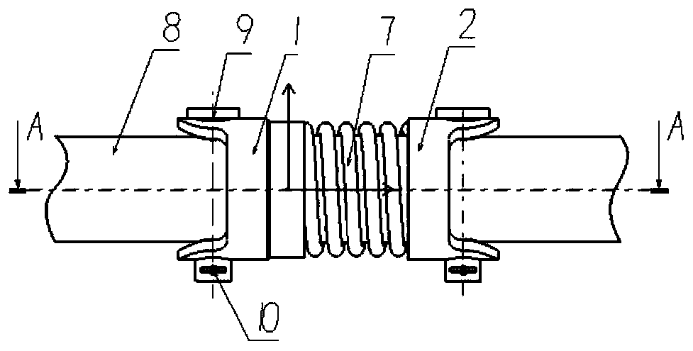
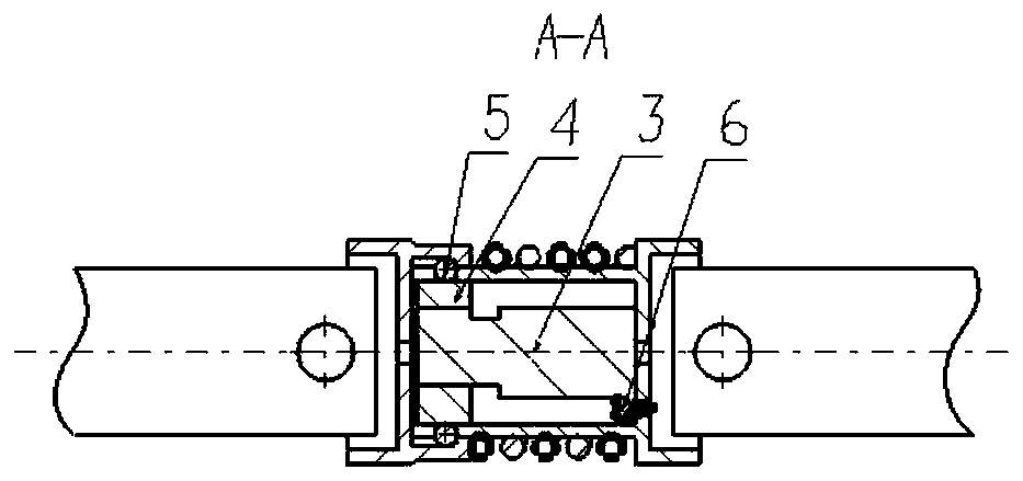
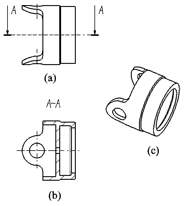
[0030] refer to Figure 1 to Figure 7 In this embodiment, the parachute automatic fall-off mechanism of the UAV is composed of the upper joint 1 of the falling joint, the lower joint 2 of the falling joint, the rotating electromagnet 3, the rotating guide rail 4, the ball 5, the screw 6, the spring 7, the umbrella belt 8, and the umbrella belt shaft 9. Composed of split pins 10; the automatic shedding mechanism is connected to the parachute umbrella belt through the shedding joint joint; the umbrella belt is connected to the drone. Among them, there are three radial lugs in the circumferential direction of the end of the rotating electromagnet 3, and an axial screw hole is opened in the center of the lugs. There are protruding pins, which are used to cooperate with the corresponding grooves of the rotating guide rail 4 to drive the rotating guide rail 4 to rotate. The...