
Material taking and placing device and material replacing device with same

A technology of picking and unloading and cranking, which is applied in the direction of packaging, etc., can solve the problems of limited space for replacement material equipment, low efficiency of picking and unloading, and no picking and unloading device, etc., to achieve compact structure, high efficiency of picking and unloading, and low cost Effect

Active Publication Date: 2019-11-22
深圳市复德科技有限公司
View PDF4 Cites 2 Cited by
  • Summary
  • Abstract
  • Description
  • Claims
  • Application Information

AI Technical Summary

Problems solved by technology

However, due to the limited space of the replacement material equipment, there is no independent pick-and-place device, and the loading carousel needs to serve as a pick-and-place device at the same time, resulting in low pick-and-place efficiency

Method used


Image

  • Material taking and placing device and material replacing device with same
  • Material taking and placing device and material replacing device with same
  • Material taking and placing device and material replacing device with same

Examples


Embodiment 1

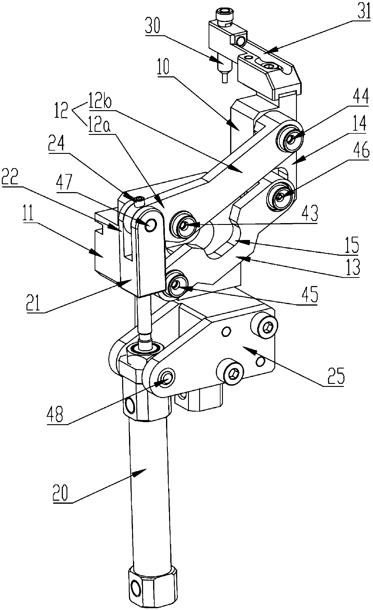
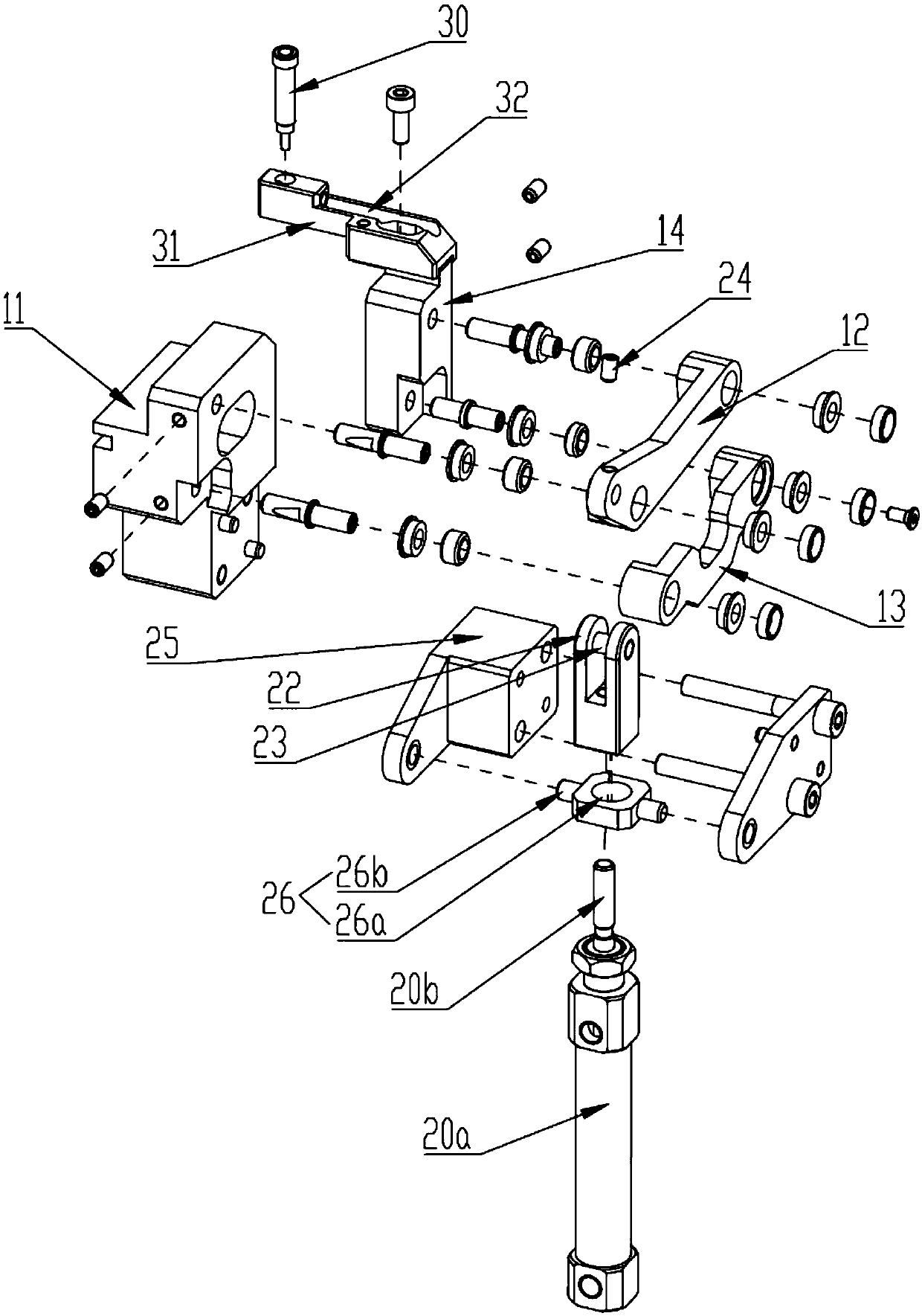
[0028] see Figure 1 to Figure 2 , the present invention provides a pick-and-place material device 40, which includes a parallelogram mechanism 10, a cylinder 20, and a suction cup 30; the parallelogram mechanism 10 includes a base 11, a first crank 12, a second crank 13 and a connecting rod 14 The first end of the first crank 12 is hinged to the first hinge point 43 of the base 11, and the second end of the first crank 12 is hinged to the second hinge point 44 of the connecting rod 14; The first end of the second crank 13 is hinged to the third hinge point 45 of the base 11, and the second end of the second crank 13 is hinged to the fourth hinge point 46 of the connecting rod 14; specifically, The projection connection line of the first hinge point 43, the second hinge point 44, the third hinge point 45 and the fourth hinge point 46 on the same plane perpendicular to the axial direction of the hinge rotation axis can always be form a parallelogram. The cylinder 20 is connec...

Embodiment 2

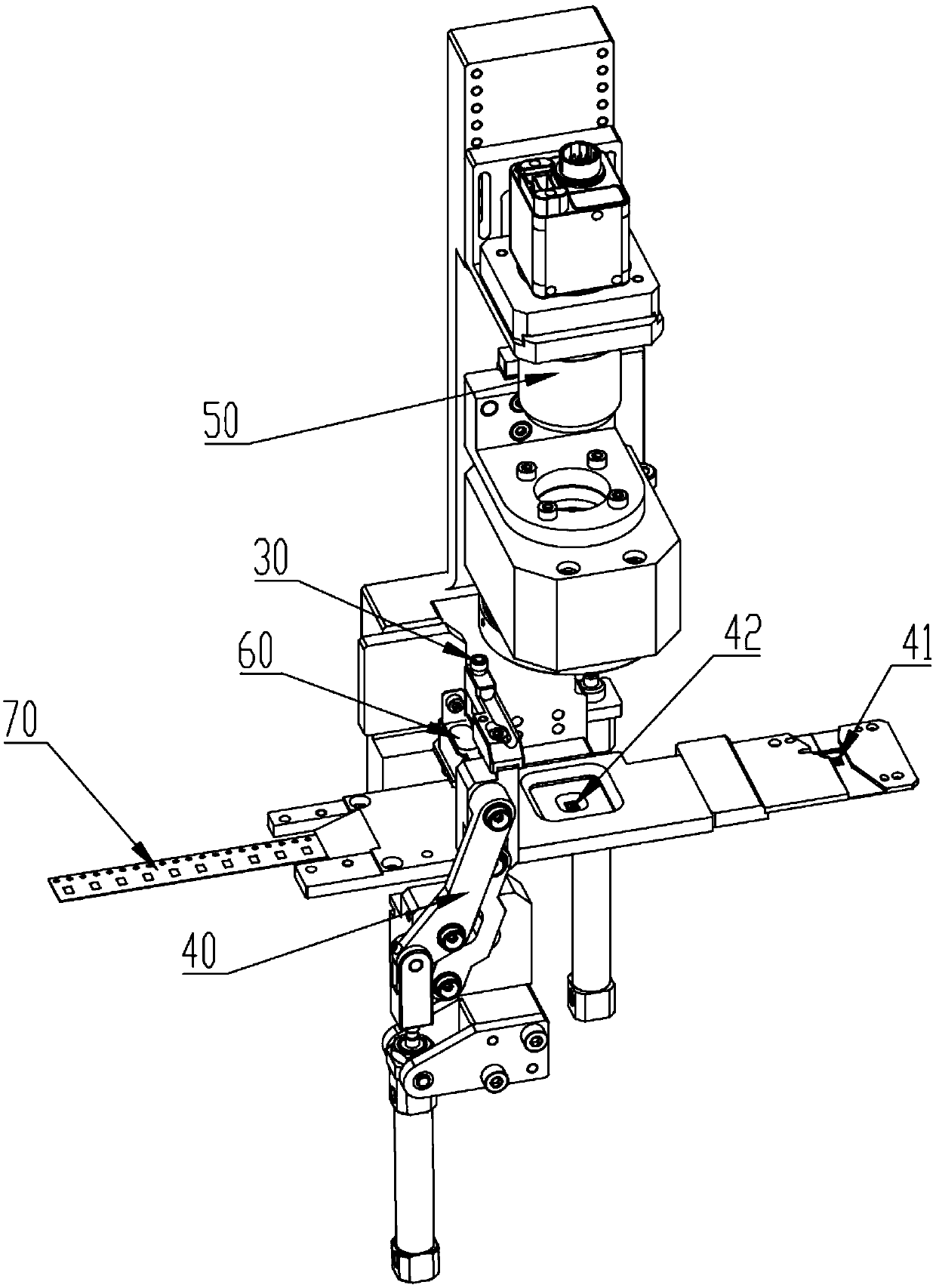
[0042] see image 3 , the present invention also provides a replacement material device, including a feeding mechanism (not shown in the figure), a carrier tape drive device (not shown in the figure) and a detection device 50, and the replacement material device also includes a Take-and-discharge device 40 with 70 take-and-discharge;

[0043] The feeding mechanism is arranged on one side of the first station 41 of the replacement material equipment, and is used to put the component to be tested on the carrier tape 70 at the first station 41;

[0044] The carrier tape driving device is connected with the carrier tape 70, and is used to drive the carrier tape 70 to move, thereby driving the component to be tested to move from the first station to the replacement device along the first direction. In the second station, the first direction is parallel to the length direction of the carrier tape;

[0045] The detection device 50 is arranged above the second station 42, and is use...


PUM


Abstract

The invention discloses a material taking and placing device and a material replacing device with the same. The material taking and placing device comprises a parallelogram mechanism, a cylinder and asucker, wherein the parallelogram mechanism comprises a base, a first crank, a second crank and a connecting rod; the first end of the first crank is hinged to a first hinging point of the base, andthe second end of the first crank is hinged to a second hinging point of the connecting rod; the first end of the second crank is hinged to the third hinging point of the base, and the second end of the second crank is hinged to the fourth hinging point of the connecting rod; the cylinder is connected with the first crank; the cylinder is capable of driving the first crank to rotate around the first hinging point; and sucker is connected with the connecting rod and used for taking and placing materials. The material taking and placing device has the advantages of being high in material takingand placing efficiency, compact in structure, low in cost and long in service life.

Description

technical field [0001] The invention relates to a pick-and-discharge device and material replacement equipment with the pick-and-discharge device. Background technique [0002] Carrier Tape refers to a strip-shaped product used in the field of electronic packaging. It has a specific thickness, and holes for holding electronic components are equidistantly distributed in its length direction and used for index positioning. the positioning hole. Carrier tape is mainly used in the electronic component placement industry. It is used with the cover tape (top sealing tape), and stores electronic components such as resistors, capacitors, transistors, and diodes in the holes of the carrier tape, and forms a closed package by sealing the cover tape above the carrier tape. Protect electronic components from contamination and damage during transportation. When electronic components are placed, the cover tape is peeled off, and the automatic placement equipment takes out the component...

Claims


Application Information

Patent Timeline
IPC IPC(8): B65B15/04B65B35/38
CPCB65B15/04B65B35/38
Inventor 龙超祥
Owner 深圳市复德科技有限公司
Learn More