Fine carving machine rack and front and back face machining process thereof

A technology of fine carving processing and fine carving machines, which is applied in the direction of manufacturing tools, tool storage devices, etc., and can solve problems such as non-stop connection

Pending Publication Date: 2020-04-17
SHENZHEN NUOFENG OPTOELECTRONICS EQUIP
View PDF6 Cites 0 Cited by
  • Summary
  • Abstract
  • Description
  • Claims
  • Application Information

AI Technical Summary

Problems solved by technology

[0003] In the process of automatic fine carving, the glass sheet of Jingdiao often adopts a multi-piece feeding method to ensure the continuous operation of automatic fine carving without stopping and the efficiency of Jingdiao work; in the actual fine carving process, there are front and back sides of the same glass Carving needs to be carried out at the same time; in the continuous and uninterrupted automatic fine carving process, there are the following technical difficulties in the process of fine carving on the front and back of the glass sheet at the same time: 1. The centralized storage method of the glass sheet; 2. The feeding and discharging methods of multiple glass sheets processed, multiple glass sheets processed on the front side and multiple glass sheets processed on the reverse side, as well as the non-stop connection problem of the different loading and unloading states of the three glass sheets

Method used


Image

  • Fine carving machine rack and front and back face machining process thereof
  • Fine carving machine rack and front and back face machining process thereof
  • Fine carving machine rack and front and back face machining process thereof

Examples


Embodiment Construction

[0021] The present invention will be further described below in conjunction with accompanying drawing:

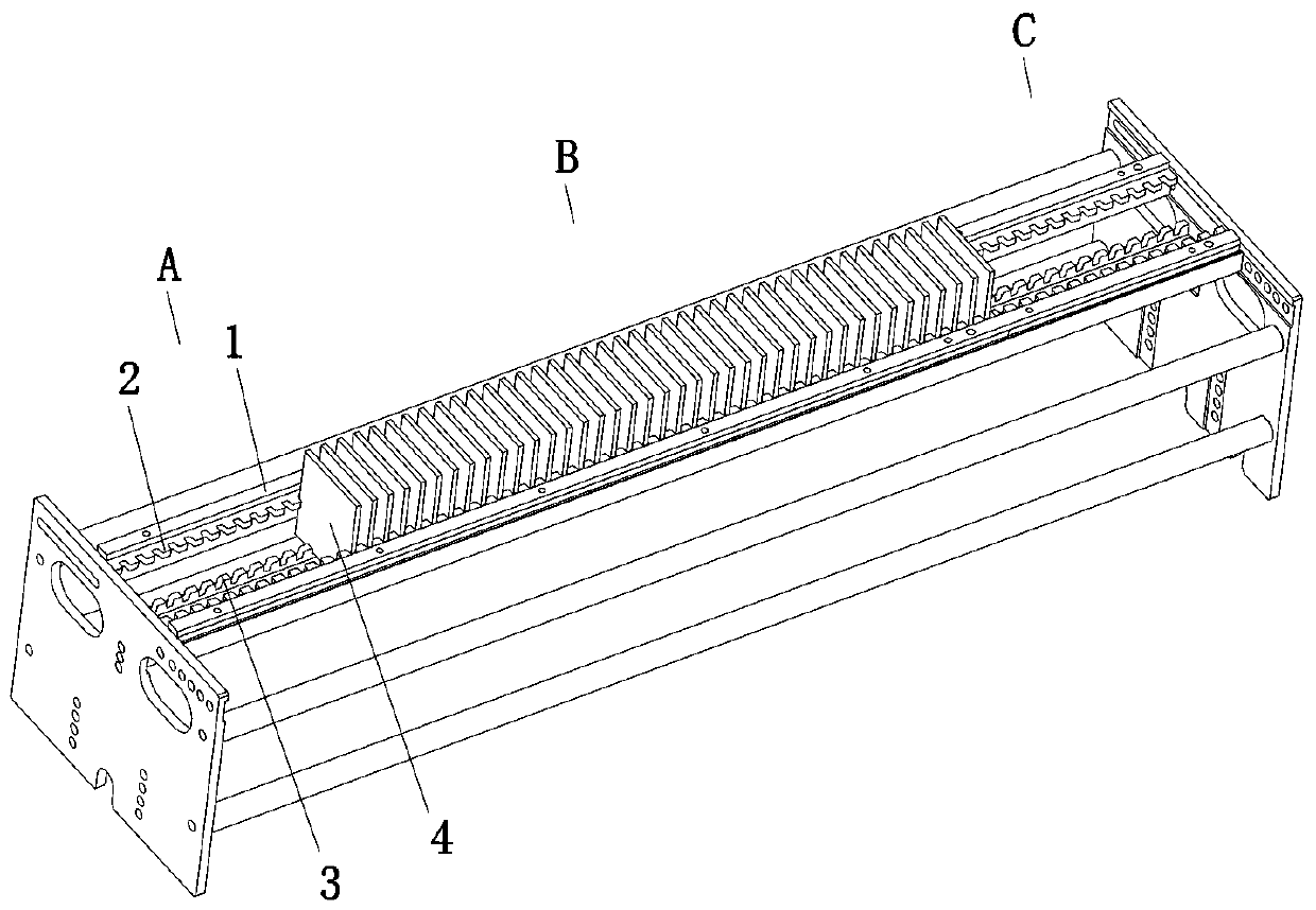
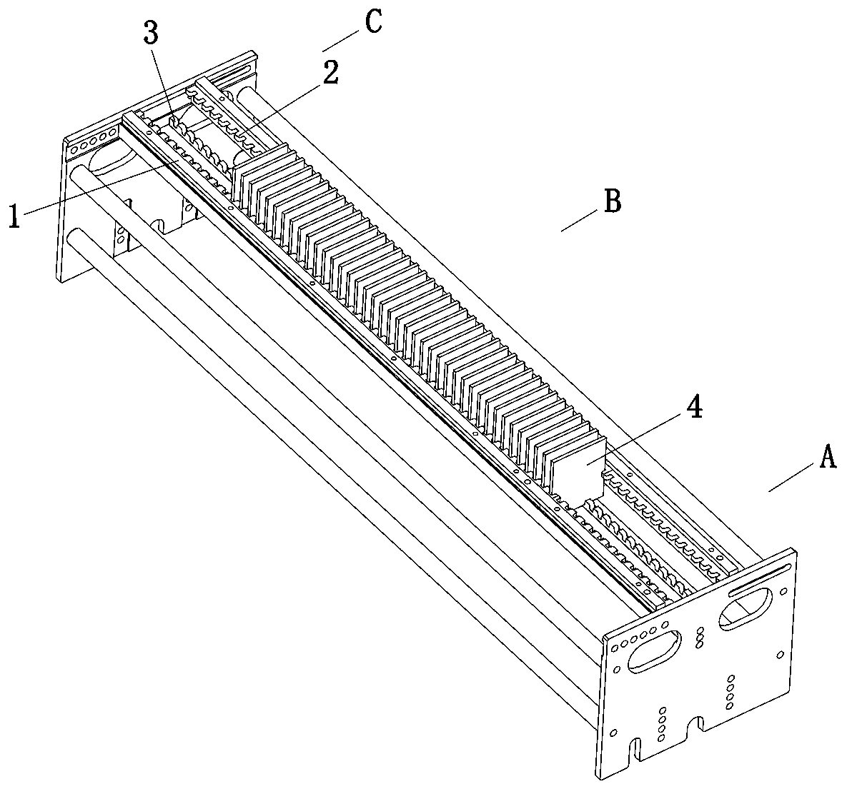
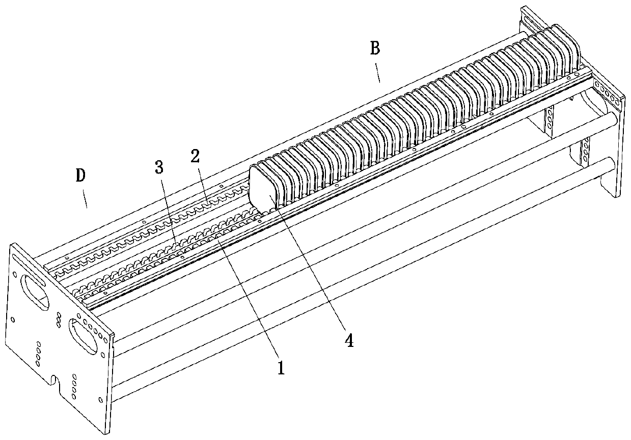
[0022] like Figure 1 to Figure 5 As shown, the technical solution adopted by the present invention is as follows: a carved machine material rack, including a frame body, an upper support bar 1, an upper limit tooth 2 and a lower limit tooth 3, wherein the above-mentioned frame body includes two parallel spaced sets The two support plates are connected and fixed by at least two connecting rods to form an overall frame structure; the upper support bar 1 includes two, the upper support bar 1 is a strip structure, and the two upper support bars 1 are arranged in parallel and spaced between two Between the support plates, a strip-shaped gap space is formed between the two upper support bars 1; the above-mentioned upper limit teeth 2 include two pieces, the two upper limit teeth are divided into 2 and are arranged along the inner sides of the two upper support bars 1, and the tw...


PUM


Abstract

The invention discloses a fine carving machine rack and a front and back face machining process thereof. The fine carving machine rack comprises a rack body, upper supporting strips, upper limiting teeth and lower limiting teeth. The rack body comprises two parallel supporting plates arranged at an interval. The two supporting plates are connected and fixed through at least two connecting rods toform an overall rack body structure. The upper limiting teeth are arranged along the inner sides of the two supporting strips. Limiting tooth grooves are formed in the two upper limiting teeth at intervals. The lower limiting teeth are arranged on the lower portion of a strip-shaped interval space, and limiting tooth grooves are arranged on the lower limiting teeth at intervals. Materials to be finely carved and materials with the finely carved front faces and back faces are vertically inserted into the strip-shaped interval space at parallel intervals and are clamped and limited by the limiting tooth grooves of the upper limiting teeth and the lower limiting teeth. The front and back face machining process comprises feeding, front face fine carving machining and back face fine carving machining. According to the fine carving machine rack and the front and back face machining process thereof, the multiple sheets of materials are vertically and freely inserted, and free switching and non-stop taking and placing of the materials to be machined and the materials with the machined front faces and back faces on the same rack are achieved.

Description

technical field [0001] The invention relates to the field of automatic manufacturing, in particular to a precision carving machine material rack and its front and back processing technology. Background technique [0002] Glass display is an important component of smart terminal equipment such as mobile phones. In recent years, with product upgrading, 3D screens have appeared. Various shapes such as ridges, depressions, and curved surfaces make the screen as a whole not on the same plane; and the existing process can only produce screen panel glass sheets with a flat structure; therefore, in order to make the traditional flat glass sheets into 3D glass However, other processing techniques are required, such as fine carving, hot pressing, etc. Among them, the fine carving process uses a specially designed blade to grind and carve on the surface of the flat glass through rotating motion to obtain 3D glass; the hot pressing process passes After the flat glass sheet is heated an...

Claims


Application Information

Patent Timeline
Patent Type & Authority Applications(China)
IPC IPC(8): B25H3/04
CPCB25H3/04
Inventor 许立峰贺谦刘秋阳王昌环宋东亮
Owner SHENZHEN NUOFENG OPTOELECTRONICS EQUIP
Why Eureka
Try Eureka