
Plate turning-over machining device and method

A processing device and processing method technology, applied to processing models, glass cutting devices, metal processing equipment, etc., can solve the problems of long processing time in the processing center, increase the processing cost of plates, and cannot be inserted back into the raw material box. The effect of improving efficiency, shortening loading and unloading time, and flexible loading and unloading methods

Pending Publication Date: 2020-05-01
江西衡源智能装备股份有限公司
View PDF2 Cites 0 Cited by
  • Summary
  • Abstract
  • Description
  • Claims
  • Application Information

AI Technical Summary

Problems solved by technology

For the same plate, two feeding and inserting operations are performed; the processing time of the machining center is long and the production efficiency is low
The processing center disclosed in this document is used to process the vehicle-mounted multimedia board. After the processing is completed, the multimedia (special-shaped) board rotates 180 degrees around its bottom edge (the edge in contact with the bottom of the material box), and its bottom edge becomes the top edge. (The bottom and the top are reversed), which will cause it to be unable to be inserted back into the raw material box, and making another material box to store the processed plate will obviously increase the processing cost of the plate and increase the storage space

Method used


Image

  • Plate turning-over machining device and method
  • Plate turning-over machining device and method
  • Plate turning-over machining device and method

Examples


Embodiment Construction

[0067] The present invention will be described in detail below in conjunction with the accompanying drawings and specific embodiments, and the schematic embodiments and descriptions of the present invention are used to explain the present invention, but are not intended to limit the present invention.

[0068] In the description of the present invention, it should be noted that if the terms "upper", "lower", "front", "rear", "left", "right", "vertical", "horizontal", "top ", "bottom", "inner", "outer", etc., the orientation or positional relationship indicated by these terms is based on the orientation or positional relationship shown in the drawings, and is only for the convenience of describing the present invention and simplifying the description, rather than indicating or It should not be construed as limiting the invention by implying that a referenced device or element must have a particular orientation, be constructed, and operate in a particular orientation.

[0069] U...


PUM


Abstract

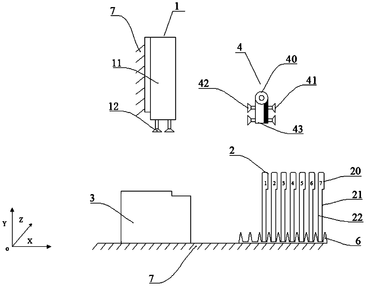
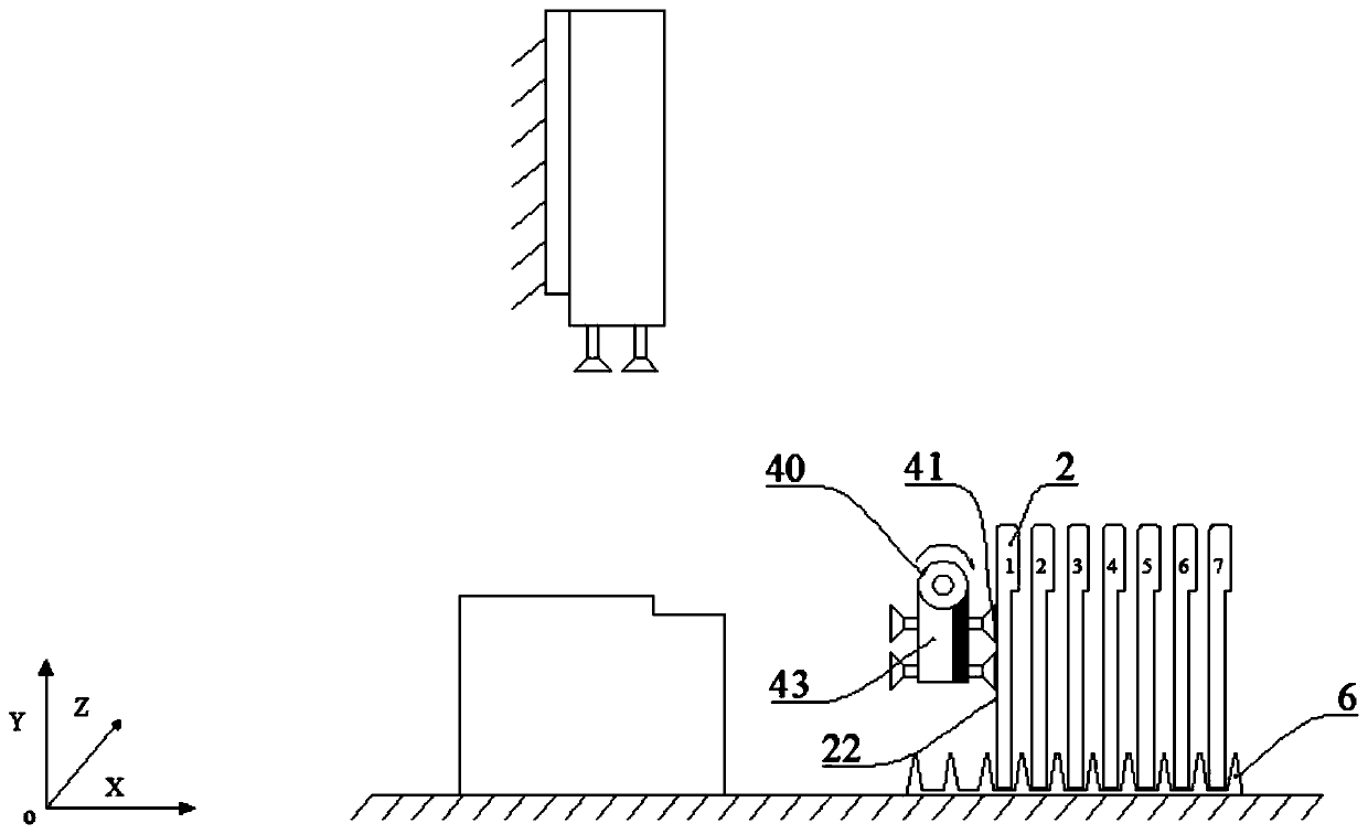
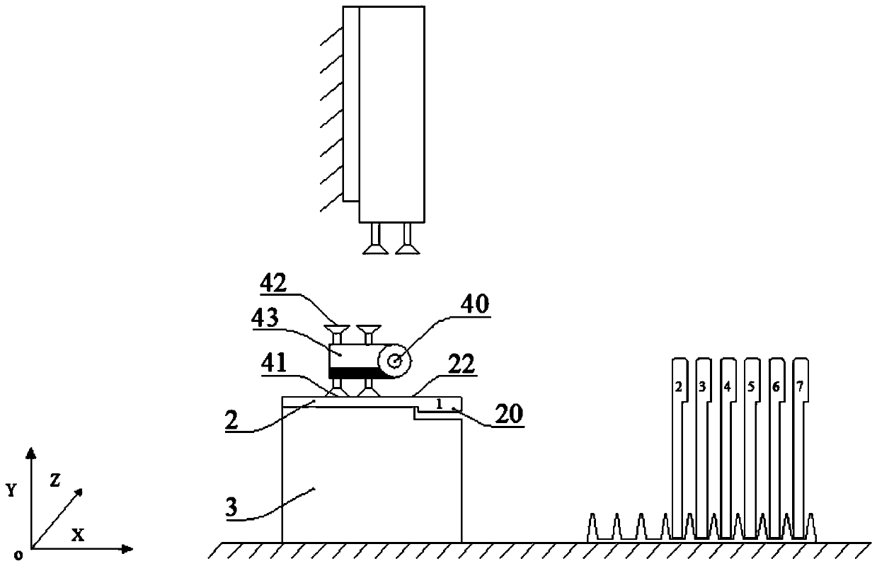
The invention provides a plate turning-over machining device and method. The plate turning-over machining device comprises a material box, a machining center, a feeding and discharging device and a turned-over plate transferring mechanism; the material box is used for storing plates before and after machining; the machining center is used for machining the surfaces of the plates placed on a machining table; the feeding and discharging device can rotate under driving of a rotating mechanism and is used for feeding and discharging the plates between the material box and the machining table; andthe turned-over plate transferring mechanism is arranged above the machining table and used for transferring the plates between the feeding and discharging device and the machining table so as to convert the machined faces and next to-be-machined faces of the plates. According to the plate turning-over machining device, by arranging the turned-over plate transferring mechanism to transfer the turned-over plates, the machining center can continuously machine the multiple faces of the same plates, thus the actuating quantity of the plate feeding and discharging device is decreased, the feeding and discharging time is shortened, and the machining efficiency is improved; and especially it can be guaranteed that after being machined, the special-shaped plates can be safely inserted into raw material grooves, and thus the material box cost and the storage space are saved.

Description

technical field [0001] The invention relates to a board material processing device, in particular to a board material turning over processing device and a processing method thereof. Background technique [0002] In liquid crystal display devices such as mobile phones and in-vehicle multimedia, the glass plates used as display panels and touch panels are produced in large batches and the delivery time is short. It is also necessary to process the glass substrate while keeping the surface of the substrate horizontal. [0003] Loading and unloading is an important process of processing machine tools. The production efficiency of sheet metal processing centers with manual loading is low, and it is difficult to meet market demand. In order to realize the high-efficiency work of the processing machine tool and realize the double-sided processing of the plate, it has always been the focus of research and development by those skilled in the art. [0004] For example, the Chinese i...

Claims


Application Information

Patent Timeline
Patent Type & Authority Applications(China)
IPC IPC(8): B44B1/06B24B41/00C03B33/03
CPCB44B1/06B24B41/005B24B41/00C03B33/03B44B2700/12
Inventor 吴勇勇王焱胡海明
Owner 江西衡源智能装备股份有限公司
Learn More