
A road cleaning electromechanical device

An electromechanical device and road technology, applied in the field of road cleaning electromechanical devices, can solve problems such as hard work and slow cleaning speed

Active Publication Date: 2020-10-27
诸暨三运针织有限公司
View PDF9 Cites 0 Cited by
  • Summary
  • Abstract
  • Description
  • Claims
  • Application Information

AI Technical Summary

Problems solved by technology

[0003] There are often foreign objects such as fallen leaves and muck on the road, which have a negative impact on the road surface environment, and the cleaning of outdoor roads and streets has always been a heavy, dangerous, dirty and tiring job, which consumes a lot of manpower and material resources. Workers can only rely on traditional brooms to clean the road surface, which is not only slow in cleaning speed, but also very hard. Therefore, in view of the above status quo, it is urgent to develop a road cleaning electromechanical device to overcome the shortcomings in current practical applications

Method used


Image

  • A road cleaning electromechanical device
  • A road cleaning electromechanical device
  • A road cleaning electromechanical device

Examples


Embodiment 1

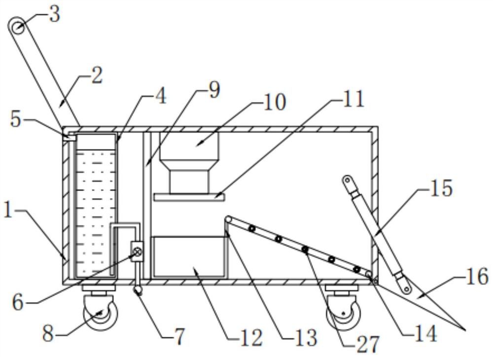
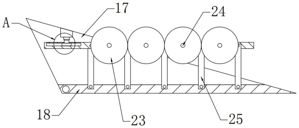
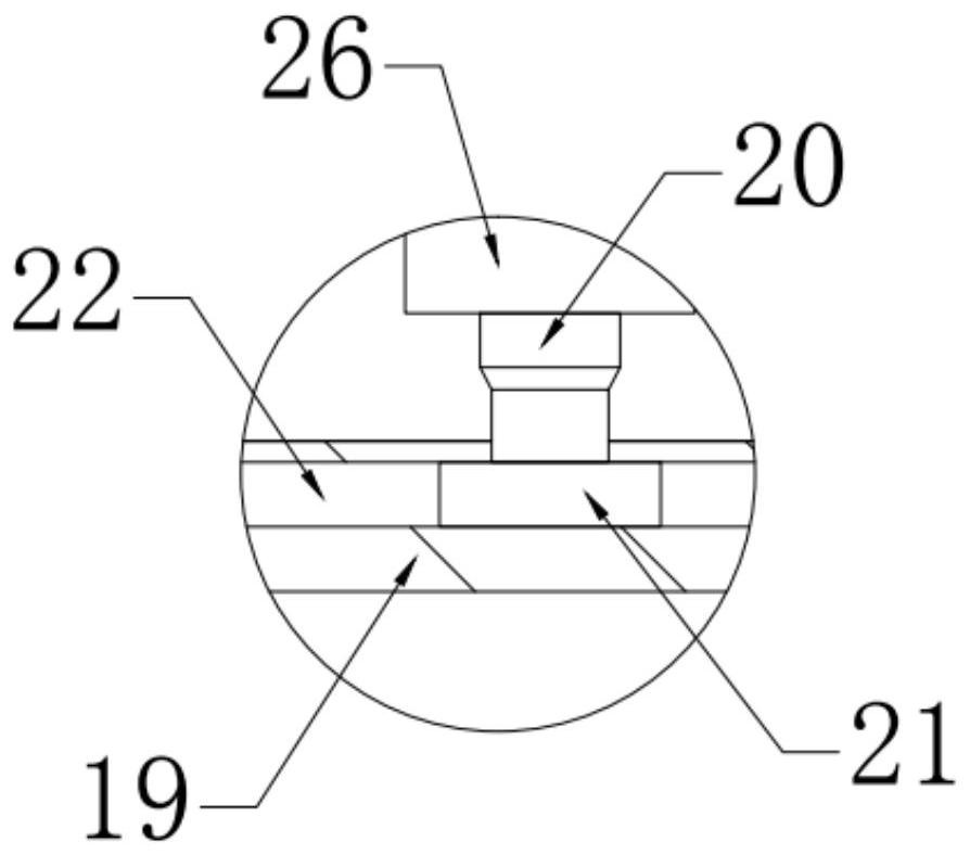
[0026] see Figure 1~3 , in an embodiment of the present invention, a road cleaning electromechanical device includes a housing 1, a partition 9 is fixedly connected to the inside of the housing 1, a cleaning mechanism is provided on the left side of the partition 9, and the partition 9 The right side is provided with a garbage disposal mechanism, and the right side of the garbage disposal mechanism is provided with a cleaning shovel 16 hinged with the housing 1, and the front and rear sides of the cleaning shovel 16 are hingedly provided with a second telescopic rod 15, and the second telescopic rod 15 is hinged. The other end of the rod 15 is hinged with the housing 1, the top of the left end of the housing 1 is fixedly connected to the front and rear sides, and the connecting rods 2 are fixedly connected, and the push handle 3 is fixedly connected between the connecting rods 2 on both sides, and the bottom of the housing 1 is provided with There are casters 8, and by settin...

Embodiment 2

[0028] In this embodiment, the cleaning mechanism includes a water tank 4 and a spray pipe 7, the water tank 4 is arranged on the left side of the partition 9, the water tank 4 is connected with the shell 1 by bolts, and the top of the left end of the water tank 4 is provided with a Through the water inlet pipe 5 of the housing 1, the right side of the water tank 4 is provided with a water pump 6 bolted to the partition plate 9, the input end of the water pump 6 and the water tank 4, the output end of the water pump 6 and the spray pipe 7 pass through The pipes are connected, and the spray pipe 7 is arranged on the lower side of the housing 1. By setting a cleaning mechanism, water can be sprinkled on the cleaned road surface, which can prevent dust from flying and maintain the road surface at the same time.

[0029] In this embodiment, the spray pipe 7 is provided with a nozzle, the nozzle is fixedly connected to the spray pipe 7, and the angle between the nozzle and the groun...


PUM


Abstract

The invention relates to the technical field of road electromechanics, and specially relates to a road cleaning electromechanical device that comprises a shell; partition plate is arranged on the inner side of the shell, a cleaning mechanism is arranged on the left side of the partition plate; a garbage treatment mechanism is arranged on the right of the partition plate; a cleaning shovel hinged to the shell is arranged on the right side of the garbage treatment mechanism; second telescopic rods are hinged to the front side and the rear side of the cleaning shovel; the other end of the secondtelescopic rod is hinged with the shell; according to the invention, the cleaning mechanism is arranged; water can be sprayed on the swept road surface; dusts can be prevented from flying, an includedangle of 30 degrees is formed between a nozzle and the ground; water sprayed by the nozzle can be prevented from splashing to pedestrians on the road surface; by arranging the cleaning shovel, foreign matter on the ground can be quickly cleaned, the workload of sanitation workers is reduced, the cleaning efficiency is improved; by arranging an adjusting mechanism, a cleaning brush can make full contact with the ground in the cleaning process, and the cleaning effectiveness of the device is guaranteed.

Description

technical field [0001] The invention relates to the field of road electromechanical technology, in particular to a road cleaning electromechanical device. Background technique [0002] From the meaning of the word, the road is the infrastructure for various trackless vehicles and pedestrians; according to its use characteristics, it can be divided into highways, urban roads, country roads, factory and mine roads, forestry roads, examination roads, competition roads, automobile test roads, workshop passages and school roads etc. [0003] There are often foreign objects such as fallen leaves and muck on the roads, which have a negative impact on the road surface environment, and the cleaning of outdoor roads and streets has always been a heavy, dangerous, dirty and tiring job, which consumes a lot of manpower and material resources. Workers can only rely on traditional brooms to clean the road surface, which is not only slow in cleaning speed, but also very hard. Therefore, i...

Claims


Application Information

Patent Timeline
Patent Type & Authority Patents(China)
IPC IPC(8): E01H1/00E01H1/04E01H1/05
CPCE01H1/00E01H1/04E01H1/05
Inventor 冯周琳岑哲
Owner 诸暨三运针织有限公司
Learn More