Closestool flushing system with direct flushing water channel and working method

A working method and toilet technology, applied in flushing toilets, flushing equipment with water tanks, water supply devices, etc., can solve the problems that the flushing force is affected by the municipal water pressure, users are troubled, and the flushing is not clean, etc., to improve the flushing effect, Effects of preventing water pollution and saving product costs

Inactive Publication Date: 2019-11-22
XIAMEN R&T PLUMBING TECH
View PDF8 Cites 0 Cited by
  • Summary
  • Abstract
  • Description
  • Claims
  • Application Information

AI Technical Summary

Problems solved by technology

[0002] In the existing direct flush toilet, the water inlet is directly connected to the tap water pipe, and the flushing force is affected by the municipal water pressure. When it is used in an environment with low pressure, it often occurs that the flushing is not clean due to the low pressure, which brings certain problems to the user. troubled

Method used


Image

  • Closestool flushing system with direct flushing water channel and working method
  • Closestool flushing system with direct flushing water channel and working method
  • Closestool flushing system with direct flushing water channel and working method

Examples


Embodiment 1

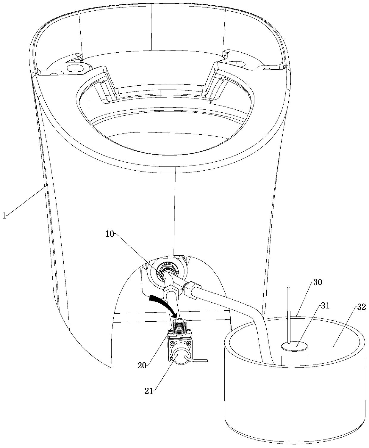
[0066] like Figure 1 to Figure 4 As shown, a toilet flushing system with a straight flush water circuit, the system includes a spray unit 10, a first water supply unit 20 and / or a second water supply unit 30, the spray unit 10 has a water outlet channel 11; the system With first mode and / or second mode:

[0067] In the first mode, the first water supply unit 20 is connected to the spray unit 10, and supplies water to the water outlet channel 11 through the first water supply unit 20;

[0068] In the second mode, the first water supply unit 20 and the second water supply unit 30 are connected to the spray unit, and supply water to the water outlet channel 11 through the first water supply unit 20 and / or the second water supply unit 30;

[0069] Alternatively, in the second mode, only the second water supply unit 30 is connected to the spray unit 10 , and water is supplied to the water outlet channel 11 through the second water supply unit 30 .

[0070] In this embodiment, th...

Embodiment 2

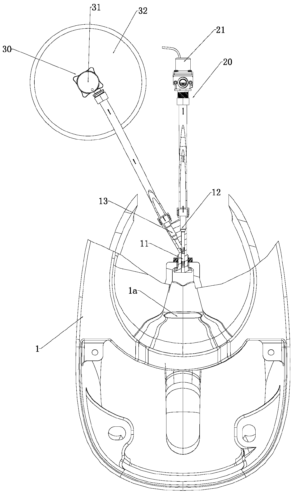
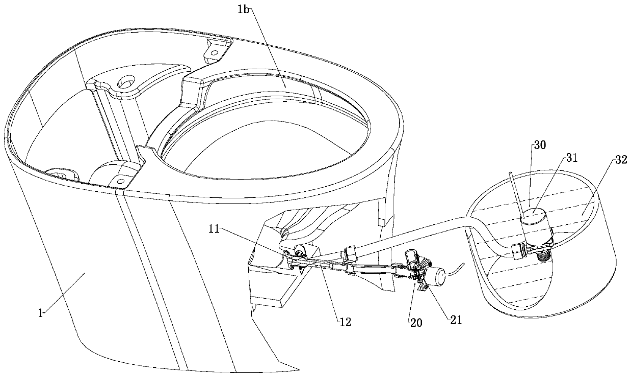
[0092] like Figure 5 to Figure 10 Shown: The main difference between this embodiment and the first embodiment is that the water tank 32 is located at the rear of the toilet 1 .

[0093] In this embodiment, the water outlet channel 11 is provided with a second anti-siphon unit 50, and the second anti-siphon unit 50 includes a second vent 51 connected to the outside world. When a negative pressure is formed in the water outlet channel 11, The outside air enters the water outlet channel 11 through the second vent 51 to form an air partition. The water outlet channel 11 and the first water inlet channel 12 are provided with the second anti-siphon unit 50 to avoid The generation of vacuum leads to siphon backflow, preventing pollution of pipes and water sources.

[0094]In other embodiments, the first water supply unit 20 and / or the first water inlet channel 12 are provided with a one-way valve and / or a first anti-siphon unit, and the one-way valve is installed in the first water...

Embodiment 3

[0101] like Figure 11 and Figure 12 As shown, the main difference between this embodiment and the first embodiment is that the first water supply unit 20 further includes a switching component 81 and a third water inlet channel 14 for supplying water to the brush ring waterway 1b. The water supply unit 20 supplies water to the first water inlet channel 12 or to the third water inlet channel 14 under the action of the switch assembly 81 . Specifically, the first water supply unit 20 includes a flush valve, the flush valve includes a valve body 80 , the switching assembly 81 is disposed on the valve body 80 , and the valve body 80 further includes a water inlet pipe 82 and a first water outlet pipe 83 and the second water outlet pipe 84, wherein the water inlet pipe 82 is communicated with the municipal water supply pipe, the first water outlet pipe 83 forms the first water inlet channel 12, and the second water outlet pipe 84 forms the third water inlet Channel 14.

[0102...


PUM


Abstract

The invention discloses a closestool flushing system with a direct flushing water channel and a working method. In a first mode, a first water supply unit is connected to a spraying unit and is used for supplying water to a water outlet channel; in a second mode, the first water supply unit and a second water supply unit are connected to the spraying unit, and the first water supply unit and/or the second water supply unit are/is used for supplying the water to the water outlet channel; or, in the second mode, only the second water supply unit is connected to the spraying unit, and is used forsupplying the water to the water outlet channel. According to the flushing system, the first mode and the second mode are set; in the second mode, the second water supply unit for supplying the waterto the water outlet channel is added, or the first water supply unit is replaced with the second water supply unit, so that the flushing force is increased, and the flushing effect of a closestool isimproved; and a user can select or replace the two modes according to actual requirements, so that the use requirements in different environments can be met, and the product cost can be reduced underthe condition that the flushing effect is satisfied.

Description

technical field [0001] The invention relates to a toilet flushing system with a straight flushing water channel and a working method. Background technique [0002] In the existing flush toilets, the water inlet is directly connected to the tap water pipe, and the flushing force is affected by the municipal water pressure. When used in a low-pressure environment, the flushing often occurs due to low pressure, which brings certain benefits to users. troubles. SUMMARY OF THE INVENTION [0003] In order to solve the above problems, the present invention provides a toilet flushing system and a working method with a straight flushing water channel. [0004] In order to achieve the above purpose, the technical solution adopted in the present invention is: a toilet flushing system with a straight flush water circuit, the system includes a spray unit, a first water supply unit and / or a second water supply unit, and the spray unit has a water outlet channel; the system has a first...

Claims


Application Information

Patent Timeline
Patent Type & Authority Applications(China)
IPC IPC(8): E03D11/02E03D11/13E03D5/00
CPCE03D5/00E03D11/02E03D11/13
Inventor 黄贵阳陈海滨钟志军
Owner XIAMEN R&T PLUMBING TECH
Why Eureka
Try Eureka