Simulation crack module and crack-type drilling fluid plugging test device

A technology for simulating cracks and testing devices, which is used in surveying, earth-moving drilling, wellbore/well components, etc., and can solve the problems of difficulty in accurately evaluating the leakage-stopping effect, false blockage, and inability to reflect the blockage of the plugging agent. To achieve the effect of important research and engineering application value

Active Publication Date: 2019-11-22
SOUTHWEST PETROLEUM UNIV
View PDF20 Cites 5 Cited by
  • Summary
  • Abstract
  • Description
  • Claims
  • Application Information

AI Technical Summary

Problems solved by technology

This plugging effect evaluation device uses artificial cracks with different widths to simulate cracks of different widths. Because the crack width is uniform and the length is only 5cm, and the material of the simulated leakage layer is steel, the crack surface is relatively smooth. The rough surface of sandstone, glutenite, and mudstone with fractured leakage is quite different, which cannot simulate the real situation of fractured leakage well. It shows that during the plugging experiment, the plugging agent cannot enter the fracture and form a false plug at the fracture opening. If the plugging agent fails to pass through the crack, the plugging effect of the plugging agent in the fracture cannot be reflected, and it is difficult to accurately evaluate the plugging effect of the plugging agent.
[0005] In response to this feature, Pu Xiaolin et al. changed the surface roughness by lengthening the length of the gap module and pasting different types and shapes of sandpaper or metal sheets inside the module, making it closer to the actual crack surface roughness, but the crack module was still fixed. The crack is wide, there is a plugging agent or it cannot enter the crack, false blockage at the crack opening, or it cannot stand in the crack, and the plugging fails.

Method used


Image

  • Simulation crack module and crack-type drilling fluid plugging test device
  • Simulation crack module and crack-type drilling fluid plugging test device
  • Simulation crack module and crack-type drilling fluid plugging test device

Examples


Embodiment Construction

[0028] The present invention will be further described below in conjunction with the accompanying drawings, but the protection scope of the present invention is not limited to the following description.

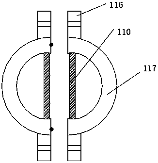
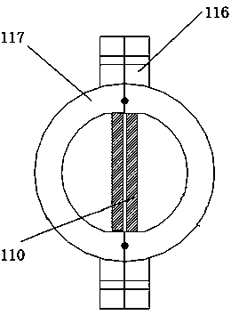
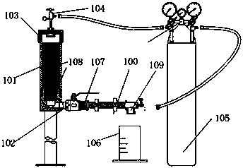
[0029] Such as Figure 1-Figure 5 As shown, a fracture-type drilling fluid plugging test device includes: a base, a sleeve 101, a sleeve cover 103, a ball valve 102 and a simulated fracture module 100. A simulated crack module 100, including: two identical semi-cylindrical members 117, in this embodiment, the material of the semi-cylindrical members 117 is metal, in other embodiments of the present invention, it can also be made of plastic or inorganic materials . In this embodiment, the two semi-cylindrical members 117 are connected by inserting positioning pins and screws into the connecting assembly 116. In other embodiments of the present invention, the two semi-cylindrical members 117 can also be connected by other detachable connection methods. A sealing groove is pro...


PUM


Abstract

The invention discloses a simulation crack module and a crack-type drilling fluid plugging test device, and relates to a drilling fluid plugging test technology. Two identical semi-cylindrical membersare included, the two semi-cylindrical members are detachably connected, a sealing groove is formed between the two semi-cylindrical members, and two rubber sealing strips used for sealing are arranged in the sealing groove. The crack section of the simulation crack module is a rectangular groove, the groove is gradually transited from deep to shallow in the depth direction, and the edge of the groove is provided with scale marks used for marking crack widths at different positions of the groove in the length direction of the groove; and the bottom of the groove is provided with an artificialsand surface for simulating the rough surface of a stratum rock crack. The crack surface roughness of different lithologies can be simulated, after a plugging experiment is completed, the simulationcrack module is opened to directly observe the plugging layer plugging agent distribution pattern, and the crack width matched with plugging slurry or a plugging agent and the plugging effect are quickly and accurately measured.

Description

[0001] Technical field: [0002] The invention relates to a drilling fluid plugging test technology, in particular to a simulated fracture module and a fracture type drilling fluid plugging test device. Background technique [0003] In the drilling construction of oil and gas wells, the downhole complex situation of fractured leakage is often encountered, which consumes expensive drilling fluid and increases drilling costs along the long drilling cycle. Usually, the plugging method to deal with fracture-type loss is to add inorganic or organic plugging materials of various shapes and particle sizes to the drilling fluid. Bridging forms the plugging layer foundation, medium particles are filled, and fine particles are blocked to form a plugging layer. The bentonite and weighting agent particles in the drilling fluid cover the plugging layer under the action of filtration to form a denser mud cake, thereby preventing the drilling fluid from omission. The particle size of the b...

Claims


Application Information

Patent Timeline
Patent Type & Authority Applications(China)
IPC IPC(8): E21B47/10E21B33/13
CPCE21B47/10E21B33/13
Inventor 邓小刚胡正文马丽华
Owner SOUTHWEST PETROLEUM UNIV
Why Eureka
Try Eureka