Method for the quality assessment of a component produced by means of an additive manufacturing method

a technology of additive manufacturing and component quality assessment, which is applied in the direction of program control, total factory control, instruments, etc., can solve the problems of component quality not being good, deviation from the target, and serious breakdown or malfunction

Active Publication Date: 2016-02-25
MTU AERO ENGINES GMBH
View PDF2 Cites 11 Cited by
  • Summary
  • Abstract
  • Description
  • Claims
  • Application Information

AI Technical Summary

Benefits of technology

[0004]The object of the present invention is to create a method by means of which an at least largely automated and quantifiable quality assessment of a component produced by means of an additive manufacturing method is made possible.
[0007]In an advantageous embodiment of the invention, an optical tomography device is used as the acquisition device. Preferably, in this case, the acquisition device affords gray-scale images with at least 16-bit depth. This makes possible a rapid and precise determination both of absolute limit values for the first data set and of actual values for the second data set.
[0009]In another advantageous embodiment of the invention, it is provided that the additive manufacturing method and / or the acquisition device is checked or monitored if the component is classified in step c1) as being fundamentally not OK. If, in step c1), it has been established that the component is fundamentally not OK because at least one actual value lies outside of the permissible range defined by the absolute limit values, it is to be assumed that there is a serious flaw in the manufacturing method and / or in the acquisition device. A check of the additive manufacturing method can comprise, for example, the examining of a laser power, the material used, or other process parameter, such as, for example, the 3D data of the component. Alternatively or additionally, the proper functioning of the acquisition device is checked. In this way, fundamental malfunctions can be identified and eliminated, as a result of which a high component quality and a low reject are ensured.
[0011]Additional advantages ensue when the mean values of the third data set are determined on the basis of actual values, which characterize an irradiated layer area of the component and / or a region of an irradiated layer area of the component. In other words, the individual component layers or subregions thereof formed during the additive manufacturing method are used as the component region. In this way, mean values that each characterize a component layer are obtained. This makes possible an especially simple and rapid quality assessment of the entire component as well as of the individual component layers, so that, when deviations are determined in a certain layer, a corresponding rapid and simple adjustment of the additive manufacturing method is made possible.
[0013]In another advantageous embodiment of the invention, it is provided that an indicator index and / or a number of indicators in the component and / or a distance from an adjacent indicator and / or a position in the component are or is used as a weighting factor. In this way, an improved weighting of flaws is made possible. In this case, the indicator index fundamentally describes a type of specific process deviation, which has a specific effect on the component. In accordance therewith, it has been shown to be advantageous when various indicator indices are used for different process deviations. The distance between adjacent indicators can be employed as a measure of the severity of an assigned process deviation or of an assigned flaw. Alternatively or additionally, the position of a process deviation or of a flaw within the component can be employed for assessment of the corresponding flaw. In this case, rear regions in the component are usually to be more strongly weighted than front regions.

Problems solved by technology

If the component has been classified as being qualitatively fundamentally not OK, it can be concluded that there is a serious breakdown or malfunction.
Alternatively, however, the assessment may also reveal that, individually or in total, the deviations deviate from the target quality so seriously that the component is to be classified as being qualitatively not OK.

Method used


Image

  • Method for the quality assessment of a component produced by means of an additive manufacturing method
  • Method for the quality assessment of a component produced by means of an additive manufacturing method

Examples


Embodiment Construction

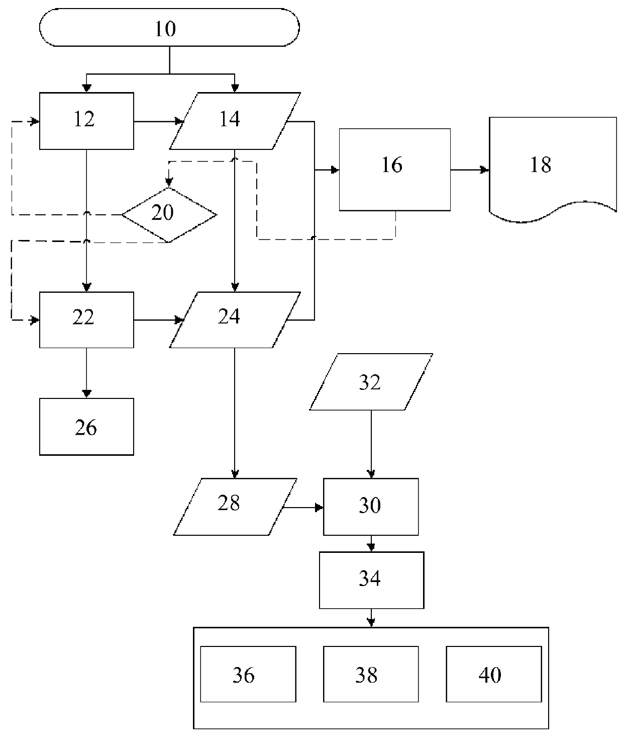
[0018]FIG. 1 shows a flow chart, which highlights in detail an exemplary embodiment of an acquisition of layer data of a generatively produced component. The method can fundamentally be carried out completely on a computer basis. The component can be a component for an aircraft engine and / or a turbomachine.

[0019]In a first step 10, an additive manufacturing of the component by means of a laser sintering and melting method, for example, is started. In this case, the component is formed in a known way iteratively from a plurality of layers on the basis of predetermined 3D design data. In step 12, a 16-bit gray-scale image is recorded for each layer n by means of an acquisition device (not shown) designed as an optical tomograph (OT), in which each pixel of the gray-scale image encodes a brightness value (actual value) at a component position of the component to be produced. All gray-scale images are compiled to obtain a second data set containing actual values. In step 14, the maximum...


PUM

PropertyMeasurementUnit
thresholdaaaaaaaaaa
areaaaaaaaaaaa
distanceaaaaaaaaaa

Abstract

The invention relates to a method for the quality assessment of a component produced by means of an additive manufacturing method. In the course of the method, it is checked first of all whether the component violates predetermined absolute limits in order to rule out the existence of serious malfunctions in the additive manufacturing process. Subsequently, a component-dependent targeting process is determined. On the basis of this targeting process, the limits for deviations are established and deviating actual values of the component are isolated and assessed by means of various parameters.

Description

BACKGROUND OF THE INVENTION[0001]The invention relates to a method for the quality assessment of a component produced by means of an additive manufacturing method.[0002]Additive manufacturing methods refer to processes in which material is deposited layer by layer on the basis of digital 3D construction data in order to build up a component generatively by 3D printing. Additive manufacturing methods thus differ from conventional material-removing or primary shaping methods of fabrication. Instead of milling a work piece from a solid block, for example, additive manufacturing methods build up components layer by layer from one or a plurality of materials. Examples of additive manufacturing methods are generative laser sintering or laser melting methods, which, for example, are used for the manufacture of components for aircraft engines. Such a method is already known from DE 10 2004 017 769 B4, for example. In selective laser melting, thin layers of powder of the material or material...

Claims


Application Information

Patent Timeline
Patent Type & Authority Applications(United States)
IPC IPC(8): G01N21/88
CPCG01N2201/12G01N21/8806G05B19/41875G05B2219/32191G05B2219/32201G05B2219/32212G05B2219/32213Y02P90/02
Inventor HESS, THOMASLADEWIG, ALEXANDER
Owner MTU AERO ENGINES GMBH
Why Eureka
Try Eureka