
car front fog lamp

A technology for front fog lights and automobiles, which is applied in the directions of headlights, motor vehicles, road vehicles, etc., can solve the problems of affecting the penetration and service life of front fog lights, unguaranteed driving safety, and increased use costs. It is convenient for normal use, enhances penetration, and prevents the effect of overheating

Active Publication Date: 2022-01-14
WUHAN CHAMPION ELECTRONICS
View PDF0 Cites 0 Cited by
  • Summary
  • Abstract
  • Description
  • Claims
  • Application Information

AI Technical Summary

Problems solved by technology

[0002] The front fog lights are installed at the front of the car at a position slightly lower than the headlights. They are used to illuminate the road when driving in rainy and foggy weather. Because the visibility in foggy days is low and the driver's sight is limited, the yellow anti-fog lights have strong light penetration. It can improve the visibility of the driver and the surrounding traffic participants, so that oncoming cars and pedestrians can find each other at a distance; therefore, the maintenance of the front fog lamps during use is particularly important. If the maintenance structure of the fog lamp structure is designed properly If it is unreasonable, it needs to be replaced frequently. On the one hand, the use cost of the car owner is increased, and on the other hand, the driving safety cannot be guaranteed; Fog lamps are kept in good condition; and due to problems such as sealing, water vapor enters, forming fog under the irradiation and heating of front fog lamps, covering the lampshade, affecting the penetration and service life of front fog lamps

Method used


Image

  • car front fog lamp
  • car front fog lamp
  • car front fog lamp

Examples


Embodiment Construction

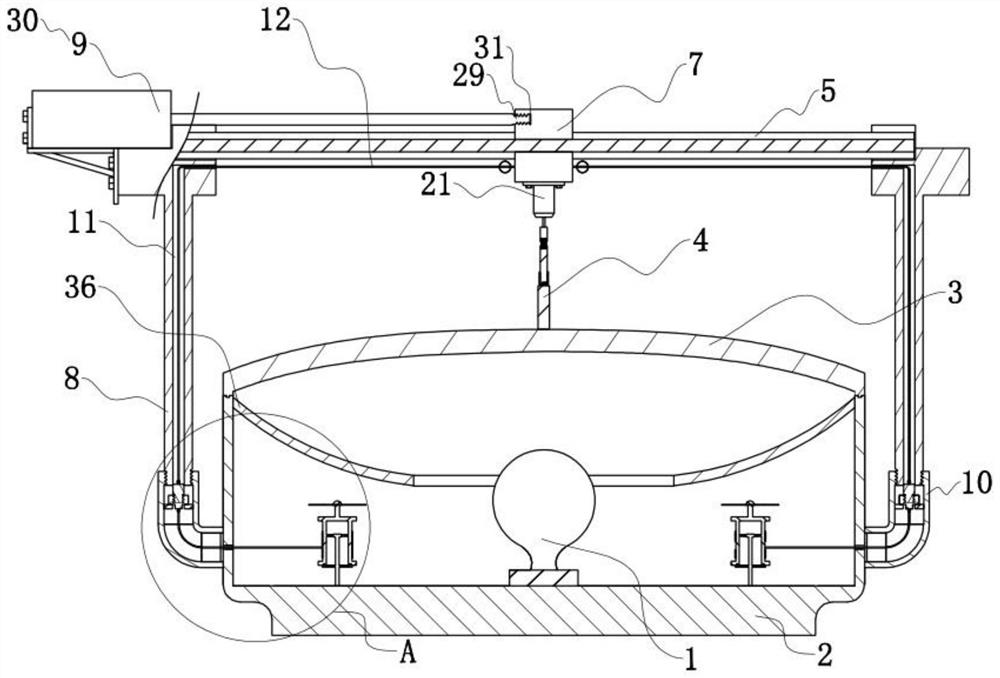
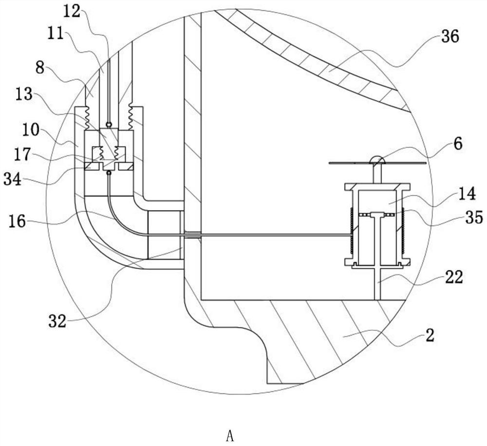
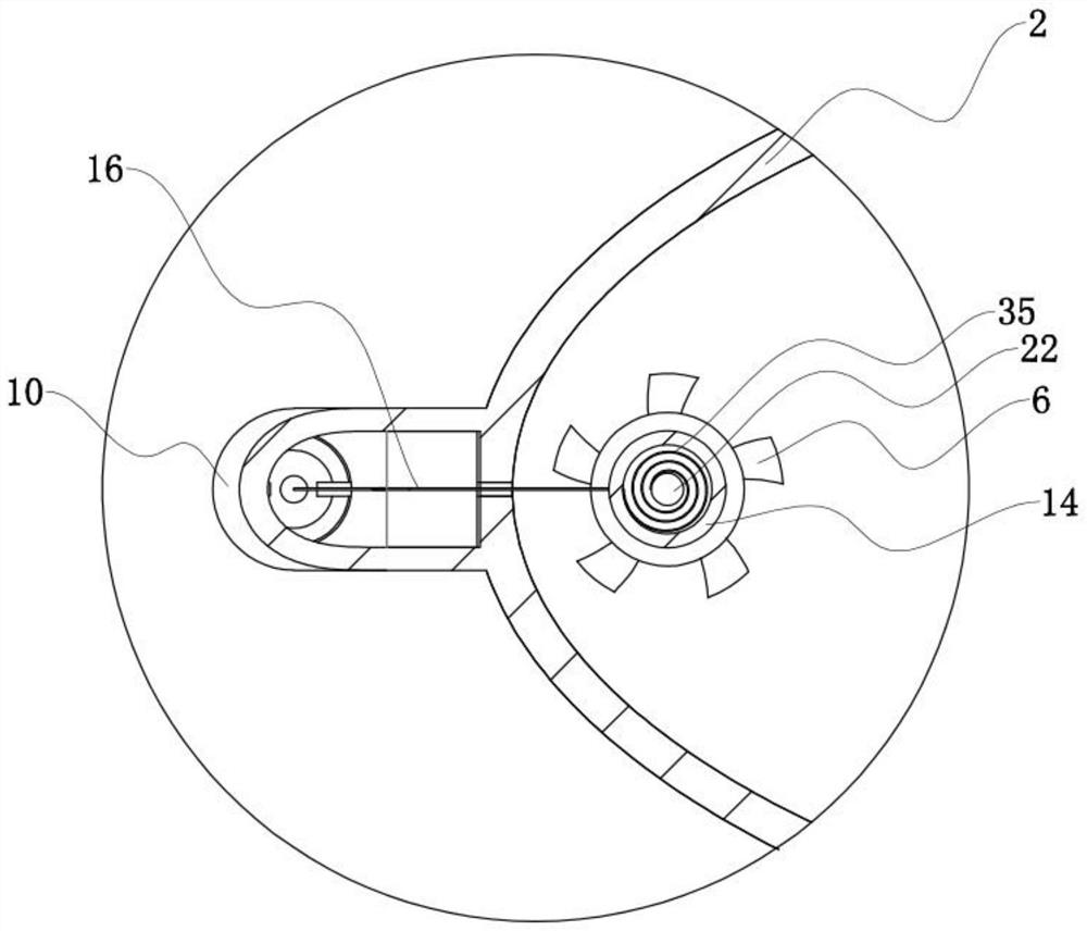
[0032] The specific implementation manners of the present invention will be further described in detail below in conjunction with the accompanying drawings and embodiments. The following examples are used to illustrate the present invention, but are not intended to limit the scope of the present invention. refer to Figure 1 to Figure 5 Further clarification on automotive front fog lamps.

[0033] A kind of automobile front fog lamp of the present invention, as figure 1As shown, it includes a bulb 1, a lamp housing 2 and a lampshade 3. The lampshade 3 is fastened with the lamp housing 2, and the inner wall of the lamp housing 2 is connected with a reflector 36; 1 is connected in the lamp housing 2, and the longitudinal section of the lamp shade 3 is arranged in an arc shape.

[0034] Such as figure 1 and figure 2 As shown, it also includes a cleaning assembly 4, a guide rail 5 arranged along the length direction of the lampshade 3, and a fan 6 located in the lamp housing...


PUM


Abstract

A kind of automobile front fog lamp of the present invention, comprises the lamp housing that is provided with reflector inside, the lamp shade that is fastened with lamp housing and the bulb that is connected with lamp housing, the guide rail that is arranged along the length direction of lamp shade and is connected with slide block, is connected with The cleaning component of the slider and the fan located in the lamp housing, the two ends of the guide rail are connected with the support rods of the driving device, the two sides of the lamp housing are connected with the fixing rings connected with the support rods, and the support rods are provided with a passage along its length direction. The two sides of the slider are connected with the first pull rope passing through the hole, the end of the first pull rope away from the slider is connected with a positioning block, the fan is fixedly connected with the roller, and the lamp housing is connected with a rotating rod connected with the roller for rotation One end of the rotating rod is located inside the drum and is connected to the inner wall of the drum through a clockwork spring. The drum is wound with a second pull rope with one end connected to the drum. The other end of the second pull rope passes through the fixing ring and is connected with a lock connected to the positioning block. Tight block; the invention integrates heat dissipation and automatic cleaning, and has the advantages of enhancing the service life of the front fog lamp of the automobile and low cost.

Description

technical field [0001] The invention relates to the technical field of automobile lamps, more specifically, it relates to an automobile front fog lamp. Background technique [0002] The front fog lights are installed at the front of the car at a position slightly lower than the headlights. They are used to illuminate the road when driving in rainy and foggy weather. Because the visibility in foggy days is low and the driver's sight is limited, the light penetration of the yellow anti-fog lights is strong. It can improve the visibility of the driver and the surrounding traffic participants, so that oncoming cars and pedestrians can find each other at a distance; therefore, the maintenance of the front fog lamps during use is particularly important. If the maintenance structure of the fog lamp structure is designed properly If it is unreasonable, it needs to be replaced frequently. On the one hand, the use cost of the car owner is increased, and on the other hand, the driving ...

Claims


Application Information

Patent Timeline
Patent Type & Authority Patents(China)
IPC IPC(8): F21S41/00F21S45/43F21S45/20F21S45/00F21V33/00F21W102/30F21W107/10
CPCF21S41/00F21S45/43F21S45/20F21S45/00F21V33/00F21W2102/30F21W2107/10
Inventor 闵烨陈明房慧冬刘勇祥贺江
Owner WUHAN CHAMPION ELECTRONICS
Learn More