Bar detection mechanism and working method thereof

A technology of bearing mechanism and moving mechanism, which is applied in the direction of conveyor objects, testing optical properties, single semiconductor device testing, etc., can solve the problems of heavy workload, low efficiency, and bar damage of operators, and achieve reasonable design and mechanism Effect

Pending Publication Date: 2019-11-22
福州中科光芯科技有限公司
View PDF0 Cites 9 Cited by
  • Summary
  • Abstract
  • Description
  • Claims
  • Application Information

AI Technical Summary

Problems solved by technology

[0003] After the bar is produced, it needs to simulate the working state (certain temperature and conductive state) to test its parameters. In the past, the bar bar is usually clamped by manual tweezers, and the bar bar is placed on a heated metal body, and it is energized, an

Method used


Image

  • Bar detection mechanism and working method thereof
  • Bar detection mechanism and working method thereof
  • Bar detection mechanism and working method thereof

Examples


Embodiment Construction

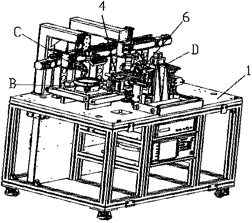
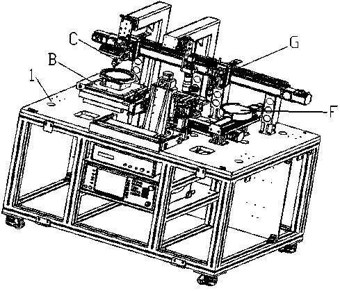
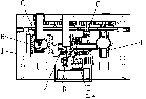
[0043] Bar bar detection mechanism of the present invention comprises frame 1 and the Bar bar carrying mechanism B (such as being located at frame 1) Figure 13 ) and Bar moving mechanism C (such as Figure 5-12 ), the frame includes a lower rectangular frame and a table top on the rectangular frame, each mechanism can be located on the table surface, and the Bar bar bearing mechanism B includes a base B1 on the frame 1 and a base B1 on the base B1. The loading tray B2 on the base, the loading tray B2 is driven by the horizontal and vertical drive mechanism B3 and the swing mechanism B4 on the base to realize the displacement of the loading tray B2; the Bar bar moving mechanism C includes 1 above the horizontal guide rail C1, the horizontal sliding seat C2 provided on the horizontal guide rail C1, and the lifting slide C3 provided on the horizontal sliding seat C2, and the lifting sliding seat C3 is provided with a bar suction head C4.

[0044] The loading tray B2 is used to ...


PUM


Abstract

The invention relates to a Bar detection mechanism and a working method thereof. The mechanism is characterized by comprising a frame, and a Bar carrying mechanism and a Bar moving mechanism which arearranged on the frame, wherein the Bar carrying mechanism includes a base arranged on the frame and a loading disc arranged on the base, the loading disc is driven and displaced by transverse and vertical driving mechanisms arranged on the base and a swinging mechanism, the Bar moving mechanism includes a transverse guide rail arranged above the frame, a transverse sliding base arranged on the transverse guide rail and a lifting sliding base arranged on the transverse sliding base, and the lifting sliding base is provided with a Bar suction head. The mechanism is advantaged in that design isreasonable, convenient and rapid Bar swinging and movement are facilitated, and later detection is facilitated.

Description

Technical field: [0001] The invention relates to a mechanism for bar detection and a working method thereof. Background technique: [0002] The bar generally refers to the LD bar, which is the semiconductor laser bar, which is mainly used in the field of 5G optical fiber communication, which can improve the communication rate. Micron. [0003] After the bar is produced, it needs to simulate the working state (certain temperature and conductive state) to test its parameters. In the past, the bar bar is usually clamped by manual tweezers, and the bar bar is placed on a heated metal body, and it is energized, and With the help of detection equipment, such as spectrum detection instruments and current detection instruments, this manual one-by-one detection method is not only inefficient, but also requires a large workload for operators, and it is easy to cause artificial damage to the bar. Invention content: [0004] Due to the deficiencies of the above-mentioned existing te...

Claims


Application Information

Patent Timeline
IPC IPC(8): G01M11/02G01R31/26B65G47/90B65G47/74
CPCB65G47/74B65G47/901G01M11/02G01R31/26
Inventor 邓艳汉
Owner 福州中科光芯科技有限公司
Why Eureka
Try Eureka