
Eureka
For R&D, Eureka makes reading and utilizing patents & technical documents easy.
Eureka AIR
Designed for self-driven R&D workflows. Generate viable solutions, solve complex R&D challenges, empower your innovation with AI.

Eureka Materials
Designed for material experts only. Revolutionize your material R&D, from search, analyze, to developing new materials.

TechResearch
Generate reliable direction feasibility study reports for your R&D in just a few steps.

TechSeek
Discover and master advanced knowledge NOW. Basics, ideas, possibilities, all at once.

TechMind
As an expert in R&D Theories, TechMind can generates customized viable solutions instantly.

TechRisk
Analyze your overall solution with one click, know your potential R&D risks in advance.

TechMonitor
Get weekly tech updates, stay abreast of the latest tech innovations and key insights.
Method for positioning failure section of high-speed railway through line
A technology for fault sections and high-speed railways, applied to fault locations, measuring devices, instruments, etc., can solve the problems of large short-circuit transition resistance, low fault location accuracy, and many power supply points, so as to achieve low cost and save faults Find the effect of time
- Summary
- Abstract
- Description
- Claims
- Application Information
AI Technical Summary
Problems solved by technology
Method used
Image

Examples
Embodiment 1
[0026] Step 1: Calculate the impedance sequence under normal operating conditions
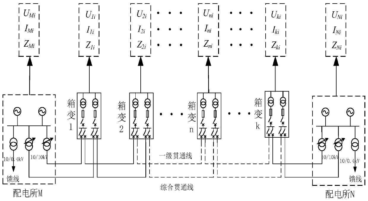
[0027] The total length of the through line is 48km, and a box-type substation is set up every 3km. Measurement points are set at the box-type substation along the power distribution station to collect real-time three-phase voltage and current values flowing through them, and calculate the three-phase " Virtual Impedance". For the convenience of description, only the "virtual impedance value" at every 6km is listed below, which does not affect the description of the embodiment.
[0028] During normal operation, due to the effect of current shunting, the farther away from the power supply, the smaller the current value of each phase; at the same time, due to the large capacitive current determined by the cable parameters, the farther away from the power supply, the voltage will gradually rise. To sum up, its "virtual impedance" sequence value has an obvious increasing trend. Table 1 calculat...
Embodiment 2
[0042] Step 1: Calculate the impedance sequence under normal operating conditions
[0043]This step is the same as that in Embodiment 1 and will not be repeated here.
[0044] Step 2: Calculate the impedance sequence under fault conditions
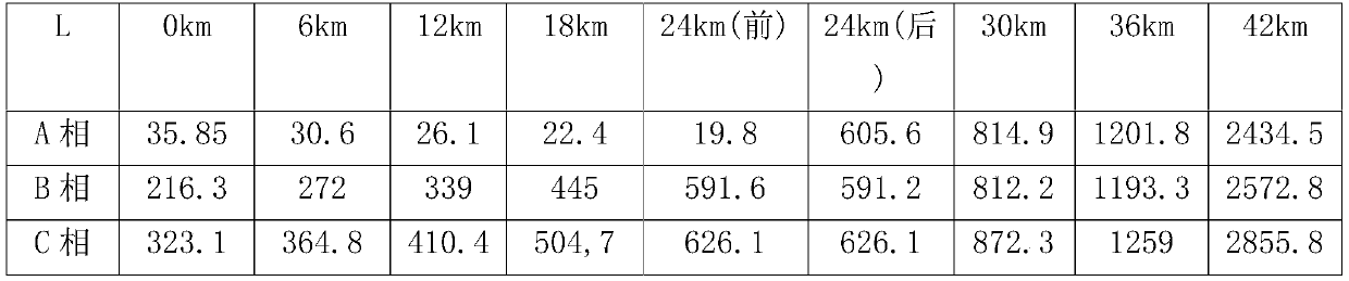
[0045] It is assumed that a two-phase short-circuit fault occurs at a distance L of 30km from the power distribution station. Calculate the "virtual impedance" of each phase voltage and current value from each measurement point. When L=30km, under the condition of AB two-phase short-circuit fault, each measurement point and each phase calculate the sequence value data of "virtual impedance" as shown in Table 3.
[0046] Table 3 Calculated impedance of each measurement point under the condition of AB fault at L=30km
[0047]
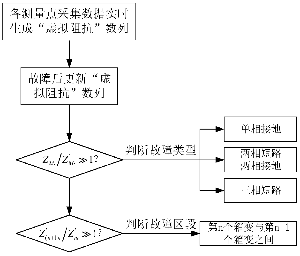
[0048] Compare the original impedance sequence value with the updated impedance sequence value after the fault, according to figure 2 The flow chart of the location of the fault section of the high-speed railw...
Embodiment 3
[0055] Step 1: Calculate the impedance sequence under normal operating conditions
[0056] This step is the same as that in Embodiment 1 and will not be repeated here.
[0057] Step 2: Calculate the impedance sequence under fault conditions
[0058] It is assumed that a three-phase short-circuit fault occurs at a distance L of 30km from the power distribution station. Calculate the "virtual impedance" of each phase voltage and current value from each measurement point. When L=30km, the sequence value data of "virtual impedance" calculated for each phase of each measurement point under the condition of three-phase short-circuit fault is shown in Table 4.
[0059] Table 4 Calculated impedance of each measurement point under the condition of ABC fault at L=30km
[0060]
[0061] Compare the original impedance sequence value with the updated impedance sequence value after the fault, according to figure 2 The flow chart of the location of the fault section of the high-speed...
PUM
 Abstract
Description
Claims
Application Information
 - R&D Engineer
- R&D Manager
- IP Professional
- Industry Leading Data Capabilities
- Powerful AI technology
- Patent DNA Extraction
Browse by: Latest US Patents, China's latest patents, Technical Efficacy Thesaurus, Application Domain, Technology Topic, Popular Technical Reports.
© 2024 PatSnap. All rights reserved.Legal|Privacy policy|Modern Slavery Act Transparency Statement|Sitemap|About US| Contact US: help@patsnap.com