Bonding protection tool and protection pasting method for rotor magnetic steel of permanent magnet motor

A technology of permanent magnet motor and magnetic steel

Active Publication Date: 2019-11-22
CSIC ELECTRICAL MACHINERY SCI & TECH
View PDF8 Cites 0 Cited by
  • Summary
  • Abstract
  • Description
  • Claims
  • Application Information

AI Technical Summary

Problems solved by technology

[0003] The invention provides a permanent magnet motor rotor magnet sticking protective tooling and a protective sticking method, which solves the problem that the pasted magnets will repel and fly out the magnets being assembled when the rotor magnets are assembled in the prior art technical problem

Method used


Image

  • Bonding protection tool and protection pasting method for rotor magnetic steel of permanent magnet motor
  • Bonding protection tool and protection pasting method for rotor magnetic steel of permanent magnet motor
  • Bonding protection tool and protection pasting method for rotor magnetic steel of permanent magnet motor

Examples


Embodiment Construction

[0022] The present invention will be described in detail below in conjunction with the drawings:

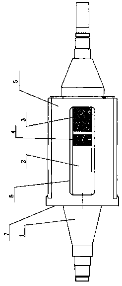
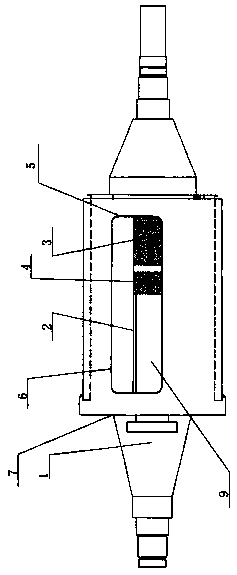
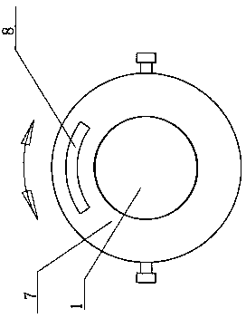
[0023] A tool for sticking and protecting permanent magnet motor rotor magnets, comprising a rotating shaft 1, a rotor core 2 is thermally sleeved on the rotating shaft 1, a sleeve 5 is movably sleeved on the rotating shaft 1, and the central axis of the sleeve 5 is connected to the rotating shaft 1 The central axes of are coincident, the sleeve 5 is rotated around the shaft 1 with the shaft 1 as the central axis, the rotor core 2 is set in the sleeve 5, and the iron core groove on the surface of the rotor core 2 and A space for magnet attachment is provided between the inner side walls of the sleeve 5, and a magnet assembly window 6 is provided on the cylindrical side of the sleeve 5 through which the magnet is attached. The outer surface of the right end of the rotor core 2 in the steel assembly window 6 is provided with a pasted magnet 3, and on the left side of the pasted magnet...


PUM


Abstract

The invention discloses a bonding protection tool and a bonding protection method for rotor magnetic steel of a permanent magnet motor, solving the problem that in the prior art, when rotor magnetic steel is assembled, bonded magnetic steel easily repels the magnetic steel which is being assembled to fly out. A sleeve (5) movably sleeves a rotating shaft (1); the sleeve (5) rotates around the rotating shaft (1) by taking the rotating shaft (1) as a central axis; a rotor core (2) is arranged in the sleeve (5); a magnetic steel assembling window (6) is arranged on the cylindrical side surface ofthe sleeve (5); bonded magnetic steel (3) is arranged on the outer surface of the right end of the rotor core (2) in the magnetic steel assembly window (6); magnetic steel (4) being assembled is arranged on the left side of the bonded magnetic steel (3) in the magnetic steel assembly window (6); and a magnetic steel assembly push rod (9) is movably inserted into a magnetic steel assembly push rodinsertion through hole (8). The personal safety of assembly personnel is ensured, and the working intensity of magnetic steel attachment is also reduced.

Description

Technical field [0001] The invention relates to a sticking protection tool for permanent magnet motor rotor magnets, in particular to a sticking protection tool for permanent magnet motor rotor magnets and a protective sticking method. Background technique [0002] Some permanent magnet motor rotors are composed of a rotating shaft, magnets, punching sheets, left and right pressure plates, and screws. After the punching sheet is tightened by four screws in the axial direction, there are eight welds on the outer circle to realize the core overlap between the magnets. The front and rear ends of the aluminum magnetic strip are connected with screws and front and rear pressure plates. The magnetic steel is bonded in the groove of the iron core with 366 anaerobic glue. The magnetic steel is axially fixed by groove-shaped block and magnetic steel pressure plate. Connect with the rear pressure plate with screws, and finally the outer surface of the rotor is fastened with carbon fiber ho...

Claims


Application Information

Patent Timeline
IPC IPC(8): H02K15/03
CPCH02K15/03
Inventor 张宏飞伍宇红张亚鸽田惠兰焦青英赵锐华
Owner CSIC ELECTRICAL MACHINERY SCI & TECH
Why Eureka
Try Eureka