Electronic equipment and signal amplification method

A technology for signal amplification and electronic equipment, applied in the field of communication, can solve the problems of increased cost of electronic equipment, increased space occupied, etc.

Active Publication Date: 2019-11-22
LENOVO (BEIJING) CO LTD
View PDF4 Cites 4 Cited by
  • Summary
  • Abstract
  • Description
  • Claims
  • Application Information

AI Technical Summary

Problems solved by technology

[0003] When the transceiver is in the sending state, both the switch 11 and the switch 12 are switched to the K1 state, and the sending signal passes through the first amplifier 13 and the second-stage amplifier 14, and finally transmits through the antenna; when the transceiver is in the receiving state, the switch 11 and

Method used


Image

  • Electronic equipment and signal amplification method
  • Electronic equipment and signal amplification method
  • Electronic equipment and signal amplification method

Examples


Embodiment Construction

[0033] In order to make the purpose, technical solutions and advantages of the embodiments of the present application clearer, the specific technical solutions of the present application will be further described in detail below in conjunction with the drawings in the embodiments of the present application. The following examples are used to illustrate the present application, but not to limit the scope of the present application.

[0034] When describing the embodiments of the present application in detail, for the convenience of explanation, the cross-sectional view showing the device structure will not be partially enlarged according to the general scale, and the schematic diagram is only an example, which should not limit the protection scope of the present application. In addition, the three-dimensional space dimensions of length, width and depth should be included in actual production.

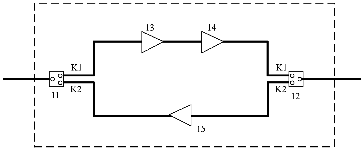
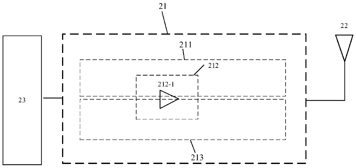
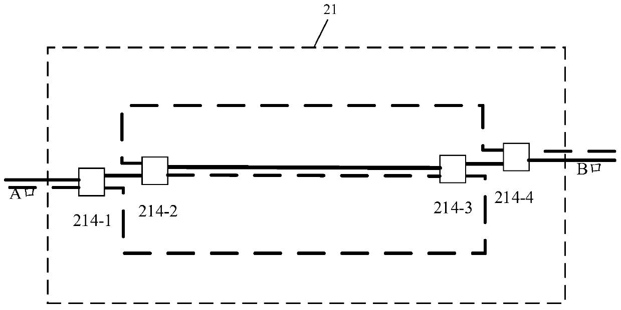
[0035] The embodiment of the present application provides an electronic device, such...


PUM


Abstract

The embodiment of the invention discloses electronic equipment. The electronic equipment comprises a radio frequency circuit arranged between an antenna and a transceiver, the radio frequency circuitcomprises an emission path comprising a signal amplification branch used for amplifying an emission signal emitted by the transceiver according to a signal amplification direction and then transmitting the emission signal to the antenna, and a receiving path comprising the signal amplification branch, wherein the signal amplification branch is used for amplifying the received signal received by the antenna according to the signal amplification direction and then transmitting the amplified signal to the transceiver; and the signal amplification branch circuit; wherein the signal amplification direction of the signal amplification branch is determined by an amplifier located in the signal amplification branch. The embodiment of the invention further discloses a signal amplification method.

Description

technical field [0001] The embodiment of the present application relates to the technical field of communication, and relates to but not limited to an electronic device and a signal amplification method. Background technique [0002] In the related art, a time division duplex (Time Division Duplexing, TDD) amplifier module, for example: a Wi-Fi front-end module, includes devices such as a switch, a power amplifier, a low noise amplifier, and a control circuit, such as figure 1 shown. [0003] When the transceiver is in the sending state, both the switch 11 and the switch 12 are switched to the K1 state, and the sending signal passes through the first amplifier 13 and the second-stage amplifier 14, and finally transmits through the antenna; when the transceiver is in the receiving state, the switch 11 and the The switches 12 are all switched to the K2 state, and the received signal reaches the transceiver through the low-noise amplifier 15; it can be seen that when sending a...

Claims


Application Information

Patent Timeline
IPC IPC(8): H04B1/40H04B1/401H04B7/155
CPCH04B1/40H04B1/401H04B7/15535
Inventor 洪晓锋
Owner LENOVO (BEIJING) CO LTD
Why Eureka
Try Eureka