Gas extraction and water drainage device and use method thereof

A gas extraction and water release technology, which is used in gas discharge, drainage, mining equipment, etc., can solve the problems of lack of auxiliary support at the bottom of the water tank, no separation of water and liquid in the water tank, and inconvenience for the fixed installation of the water tank.

Active Publication Date: 2019-11-26
NORTH CHINA INST OF SCI & TECH
View PDF6 Cites 0 Cited by
  • Summary
  • Abstract
  • Description
  • Claims
  • Application Information

AI Technical Summary

Problems solved by technology

[0005] In order to solve the above-mentioned technical problems, the present invention provides a gas drainage water release device and its use method to solve the inconvenience of fixing and installing the water tank in the existing technology, the lack of separation of the water and liquid in the water tank and the inability to The problem that the bottom of the water tank plays an auxiliary support role, a gas drainage and regeneration device, including gas drainage pipe, funnel tee pipe, flange connection plate, U-shaped conduit, airtight plug, auxiliary fixing frame structure, non-slip blind hole , a water storage device, a valve, a mounting plate, a switch on the left, a switch on the right and an adjustable auxiliary support structure, the funnel tee pipe is installed in the middle of the inner side of the gas drainage pipe through a flange connection plate bolt; The U-shaped conduit is welded on the lower part of the funnel tee; the airtight plug is plugged into the upper right side of the U-shaped conduit; the auxiliary fixing frame structure is sleeved on the outer upper part of the U-shaped conduit; The non-slip blind hole is opened on the left side of the front part of the U-shaped conduit; the water storage device is arranged on the lower outside of the U-shaped conduit and installed on the lower part of the auxiliary fixing frame structure; the valve is threaded on the U-shaped The left upper part of the conduit; the left switch and the right switch are respectively screw-mounted on the left side of the mounting plate; the adjustable auxiliary bracket structure is installed on the lower part of the water storage device; the water storage device It includes a water storage tank, a longitudinal partition, a U-shaped aqueduct, a left water pump and a right water pump. The U-shaped aqueduct is plugged into the lower part of the front side of the water storage tank; In the lower part of the front side of the water storage tank, and connected to the U-shaped aqueduct on the left and right sides; the mounting plate screws are installed in the lower left side of the water storage tank

Method used


Image

  • Gas extraction and water drainage device and use method thereof
  • Gas extraction and water drainage device and use method thereof
  • Gas extraction and water drainage device and use method thereof

Examples


Embodiment Construction

[0037] The present invention will be further described below in conjunction with accompanying drawing:

[0038] In the picture:

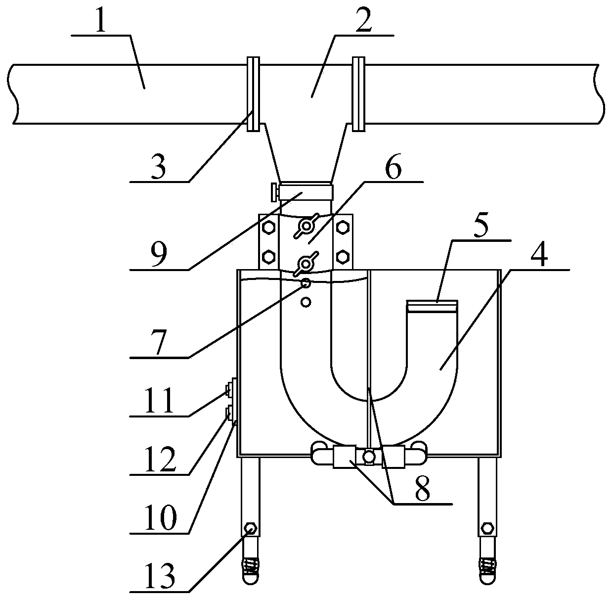
[0039] as attached figure 1 And attached image 3 shown

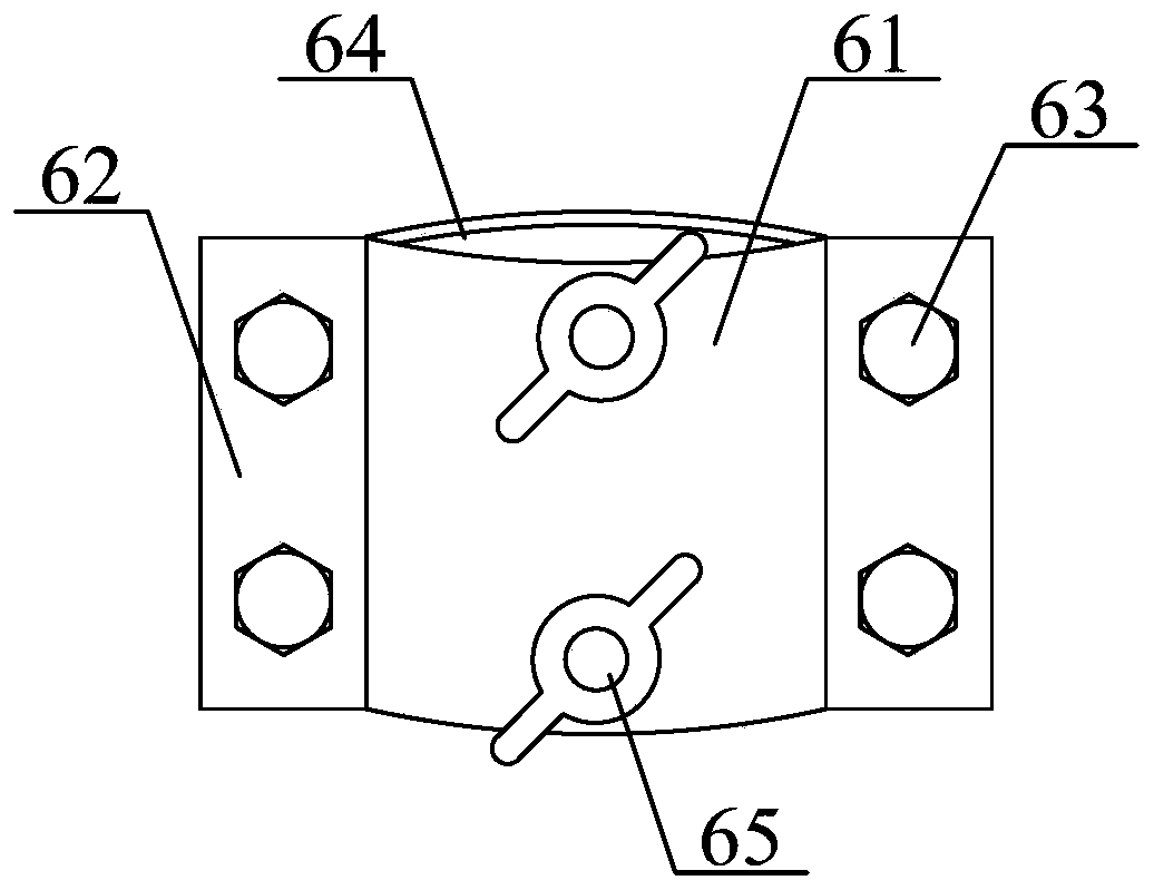
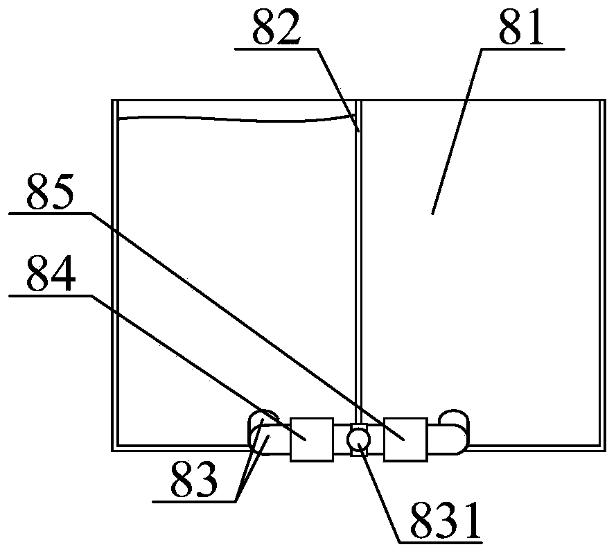
[0040] The present invention provides a gas extraction and regeneration device, which includes a gas extraction pipe 1, a funnel tee pipe 2, a flange connection plate 3, a U-shaped conduit 4, an airtight plug 5, an auxiliary fixing frame structure 6, and an anti-slip blind hole 7 , a water storage device 8, a valve 9, a mounting plate 10, a left switch 11, a right switch 12 and an adjustable auxiliary bracket structure 13, and the funnel tee pipe 2 is installed on the gas pump through a flange connecting plate 3 bolts The inner middle position of the sampling pipe 1; the U-shaped conduit 4 is welded on the lower part of the funnel tee pipe 2; the airtight plug 5 is inserted on the upper right side of the U-shaped conduit 4; the auxiliary fixing frame The structure 6 is sleeved on the oute...


PUM


Abstract

The invention provides a gas extraction and regeneration device, comprising a gas extraction pipe, a funnel tee pipe, a flange connecting plate, a U-shaped conduit, a gas tight plug, an auxiliary fixed frame structure, a non slip blind hole, a water storage device, a valve, a mounting plate, a left switch, a right switch and an adjustable auxiliary support structure. The funnel tee pipe is installed in the middle position of the inside of the gas extraction pipe through a bolt of the flange connecting plate, the U-shaped conduit is welded to the lower part of the funnel tee pipe, the air tightplug is connected to the upper right side of the U-shaped conduit in an inserting mode, and the auxiliary fixed frame structure is connected to the outer upper part of the U-shaped conduit in a sleeving mode. According to the device, a fixing hoop is connected to the outside of the U-shaped conduit in a sleeving mode, the bolt and a nut are conducive to be tighten on a fixing side plate during use, so as to facilitate installation of a water storage tank; and a longitudinal partition plate is longitudinally embedded in the middle position of the inner part of the water storage tank, and the separation effect of water in the left and right sides of the water storage tank is conducive to be achieved during use.

Description

technical field [0001] The invention belongs to the technical field of gas drainage, and in particular relates to a gas drainage water release device and a use method thereof. Background technique [0002] Since the pressure in the gas drainage pipeline is in a negative pressure state, the moisture in the coal seam will be pumped into the drainage pipeline to form water accumulation during gas extraction, thereby reducing the gas storage space in the drainage pipeline. Therefore, it is necessary to regularly discharge the accumulated water in the extraction pipeline. [0003] However, the existing technology has the problems of inconvenient fixed installation of the water tank, lack of separation of water and liquid in the water tank and lack of auxiliary support for the bottom of the water tank. [0004] Therefore, it is very necessary to invent a kind of gas extraction water release device and its using method. Contents of the invention [0005] In order to solve the a...

Claims


Application Information

Patent Timeline
Patent Type & Authority Applications(China)
IPC IPC(8): E21F7/00E21F16/00
CPCE21F7/00E21F16/00
Inventor 陈鹏刘永杰陈学习谢宏杨涛
Owner NORTH CHINA INST OF SCI & TECH
Why Eureka
Try Eureka