
A high-pressure centrifugal hydraulic pump

A centrifugal force and hydraulic pump technology, applied in the field of hydraulic pumps, can solve problems such as large energy consumption, and achieve the effects of reducing energy loss, reducing density, and reducing load

Active Publication Date: 2021-09-07
杨甫在
View PDF7 Cites 0 Cited by
  • Summary
  • Abstract
  • Description
  • Claims
  • Application Information

AI Technical Summary

Problems solved by technology

[0004] The purpose of the present invention is to provide a high-pressure centrifugal hydraulic pump to solve the problem of large energy consumption in existing centrifugal pumps

Method used


Image

  • A high-pressure centrifugal hydraulic pump
  • A high-pressure centrifugal hydraulic pump

Examples


Embodiment Construction

[0021] The following is further described in detail through specific implementation methods:

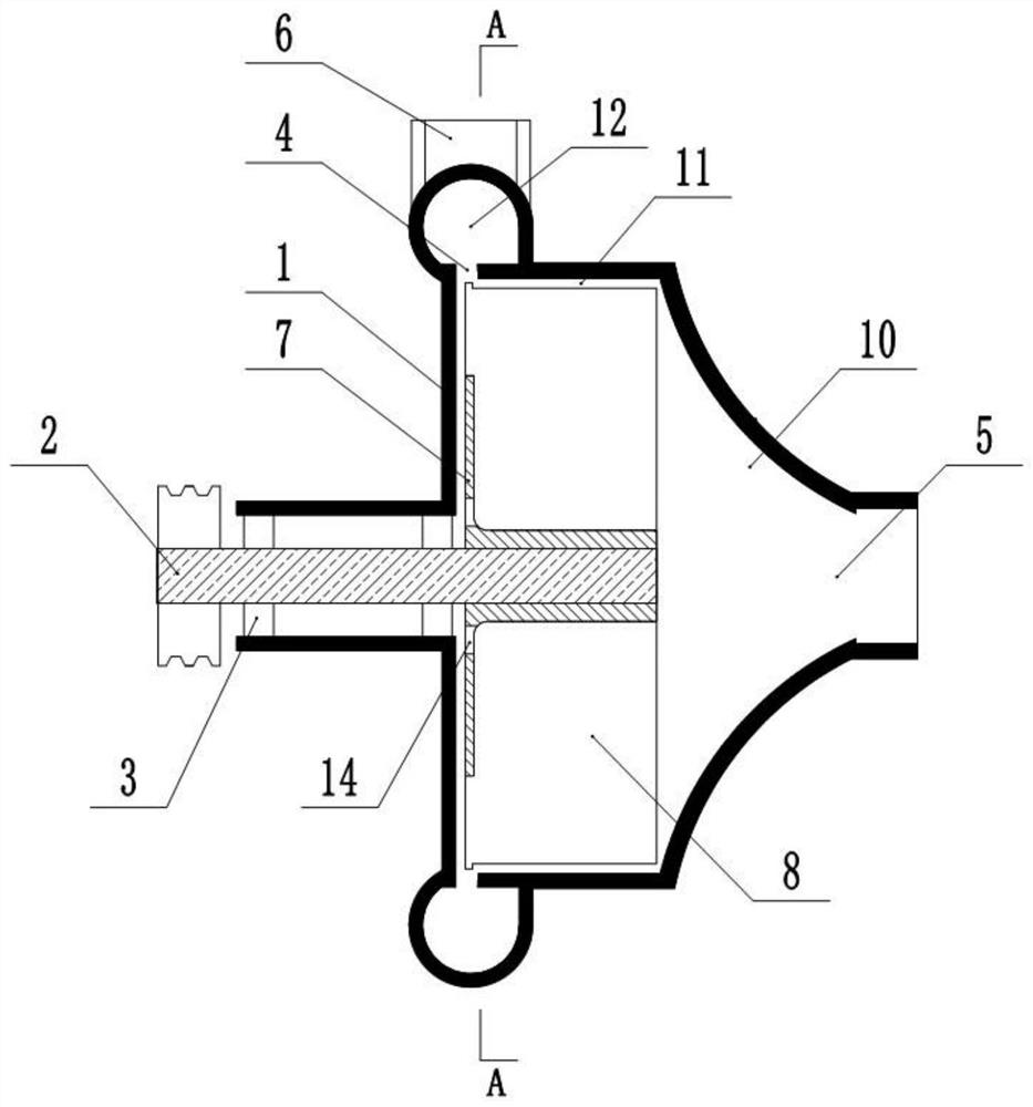
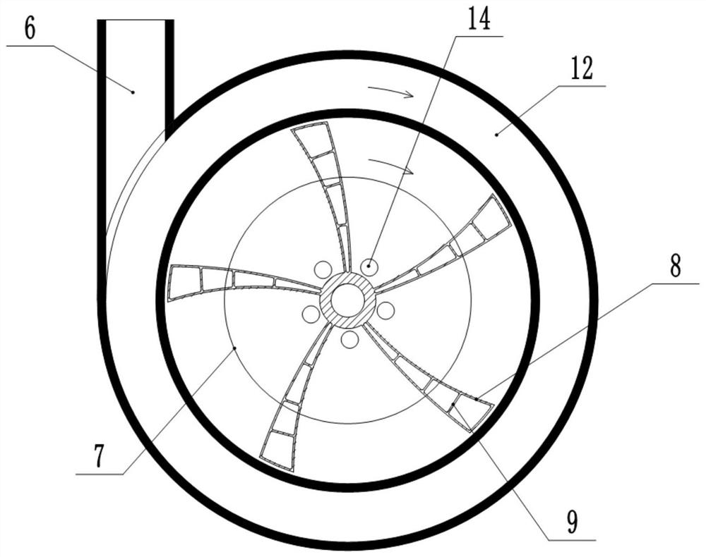
[0022] The reference signs in the accompanying drawings of the specification include: pump casing 1, pump shaft 2, bearing 3, flow-restricting channel 4, inlet 5, outlet 6, reinforcing rib 7, blade 8, connecting plate 9, front chamber 10, impeller chamber 11 , Runner 12.

[0023] The embodiment is basically as attached figure 1 , figure 2 Shown:

[0024] A high-pressure centrifugal hydraulic pump, including a pump casing 1, a pump shaft 2, a bearing 3, an impeller, an inlet 5 and an outlet 6, the bearing 3 is fixedly connected to the pump casing 1, the pump shaft 2 is connected in the bearing 3 and passed through the motor or engine Drive, a sealing ring is provided between the bearing 3 and the pump casing 1. The impeller is fixedly sleeved on the pump shaft 2 and located in the pump casing 1. The impeller is fixedly connected with a reinforcing rib 7, and the reinforcing rib 7...


PUM


Abstract

The invention relates to the technical field of hydraulic pumps, and discloses a high-pressure centrifugal force hydraulic pump, which includes a pump casing, a pump shaft, a bearing, an impeller, an inlet and an outlet, the bearing is fixedly connected to the pump casing, the pump shaft is connected in the bearing, and the impeller is fixedly connected On the pump shaft, the impeller includes hollow and sealed blades. The pump casing is formed with a front chamber, an impeller chamber and a flow channel in sequence from the inlet to the outlet. The impeller chamber and the flow channel are connected with a flow-limited passage. The invention can effectively reduce energy loss by setting open impellers and flow-limiting passages.

Description

technical field [0001] The invention relates to the technical field of hydraulic pumps, in particular to a high-pressure centrifugal force hydraulic pump. Background technique [0002] A centrifugal pump refers to a pump that delivers liquid by the centrifugal force generated when the impeller rotates. The existing centrifugal pump sucks the liquid from the center of the circle, passes through the semi-open impeller, and through the rotation of the impeller, the liquid is thrown from the center of the impeller to the outer edge of the impeller and flows out along the discharge port with a higher pressure. [0003] The above-mentioned existing centrifugal pump, because there is no higher design for the size of the impeller outlet, and the impeller with a semi-open structure, causes excessive energy loss during high-speed rotation, and due to the centrifugal force, the loss of the bearing Also big. Moreover, when high pressure is required, multi-stage centrifugal pumps or mu...

Claims


Application Information

Patent Timeline
Patent Type & Authority Patents(China)
IPC IPC(8): F04D29/22F04D29/24F04D29/42
CPCF04D29/2222F04D29/24F04D29/426
Inventor 杨甫在
Owner 杨甫在
Learn More