Supercharge Your Innovation With Domain-Expert AI Agents!

Vibrator unit and vibrating body holding structure

A vibrating body, an integrated technology, which is applied to the arrangement of engine components, non-rotational vibration suppression, and cooling and combination of power units, can solve problems such as reduced durability, and achieve simplified vibrating bodies, improved assembly, and reduced costs. Effect

Active Publication Date: 2022-01-07
HONDA MOTOR CO LTD
View PDF10 Cites 0 Cited by
  • Summary
  • Abstract
  • Description
  • Claims
  • Application Information

AI Technical Summary

Problems solved by technology

When the vibration generated by the EWP is transmitted to the vehicle body via the bracket, etc., the vibration may be perceived by passengers as abnormal noise, or the durability of the mounting part between the vehicle body and the bracket may decrease.

Method used


Image

  • Vibrator unit and vibrating body holding structure
  • Vibrator unit and vibrating body holding structure
  • Vibrator unit and vibrating body holding structure

Examples


Embodiment Construction

[0036] Hereinafter, embodiments of the present invention will be described based on the drawings. In addition, in each embodiment described below, the same code|symbol is attached|subjected to the corresponding structure in some cases, and description is abbreviate|omitted.

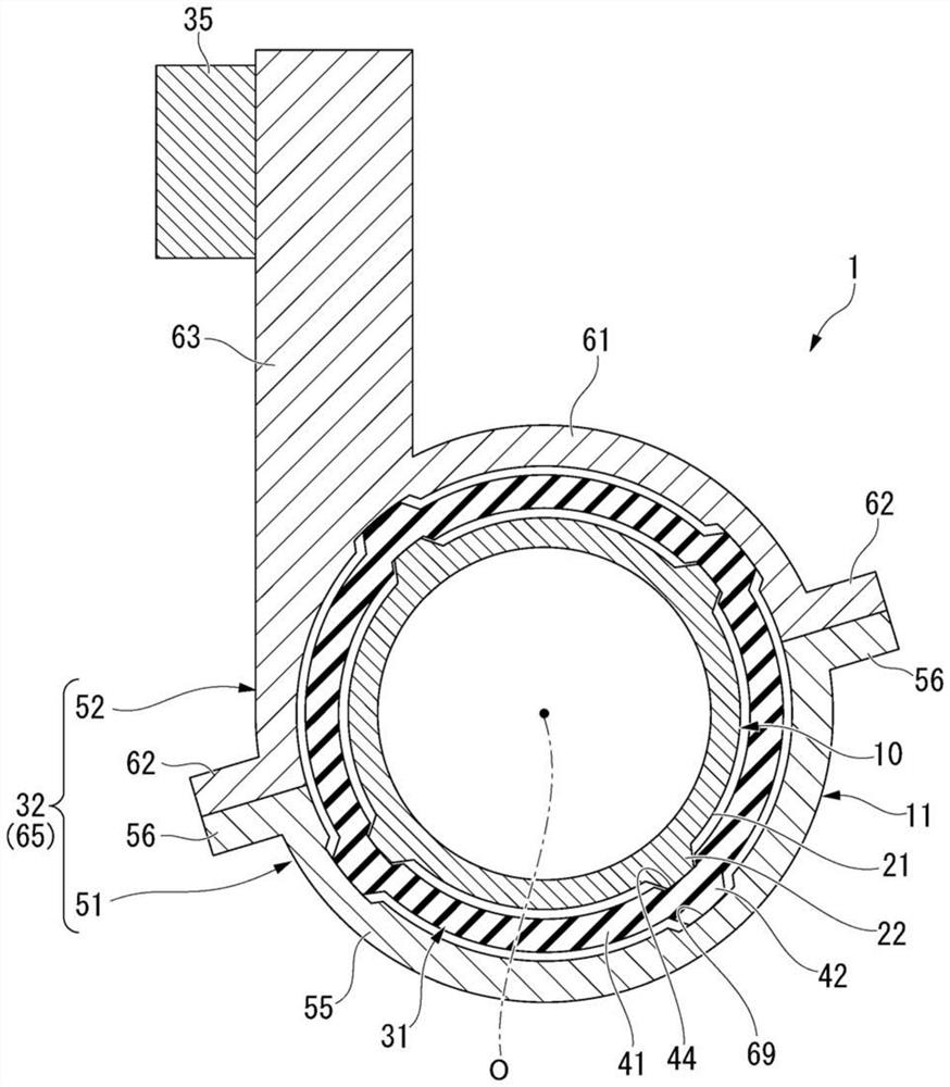
[0037] figure 1 is a schematic sectional view of the pump unit 1 .

[0038] figure 1 The illustrated pump unit (vibrator unit) 1 is mounted, for example, in an engine compartment of a vehicle. Specifically, the pump unit 1 of the present embodiment includes an EWP (vibrator) 10 and a vibrating body holding structure 11 that attaches the EWP 10 to a vehicle body.

[0039]

[0040] The EWP 10 is installed on a cooling circuit that connects a radiator to a cooling target (for example, an engine, an inverter, etc.). EWP10 pressurizes the cooling water flowing in the cooling circuit. The EWP 10 includes a cylindrical case 21 . In the following description, the direction along the axis O of the housin...


PUM


Abstract

To provide a vibrating body unit and a vibrating body holding structure capable of further improving the vibration absorbing performance and stably supporting the vibrating body. The vibrating body unit (1) has: a vibrating body (10); an inner cylinder (41) that surrounds the vibrating body (10) and is elastically deformable; an outer cylinder (65) that surrounds the inner cylinder (41). cylinder (41), and has a mounting portion (63) installed on the base portion (35); a plurality of first spacers (22), which are interposed between the vibrating body (10) and the inner cylinder ( 41), and arranged at intervals in the circumferential direction; a plurality of second spacers (42), which are interposed between the inner cylinder (41) and the outer cylinder (65), and are arranged in the circumferential direction The plurality of first spacers (22) and the plurality of second spacers (42) are arranged at intervals, and at least a part thereof is radially opposed to each other across the inner cylinder (41). Location.

Description

technical field [0001] The present invention relates to a vibrating body unit and a vibrating body holding structure. Background technique [0002] Among components mounted on a vehicle, there are components (vibrator) that are accompanied by vibration during operation. As an oscillating body, there is, for example, an electric water pump (hereinafter referred to as EWP) that circulates cooling water between a radiator and a cooling target (for example, an engine, an inverter, etc.). In the EWP, for example, when a motor mounted on the EWP rotates, vibrations are generated due to pulsation of cooling water passing through the EWP or the like. When the vibration generated by the EWP is transmitted to the vehicle body via the bracket or the like, passengers may perceive the vibration as abnormal noise, or the durability of the mounting portion between the vehicle body and the bracket may decrease. [0003] Then, for example, Japanese Unexamined Patent Publication No. 2003-40...

Claims


Application Information

Patent Timeline
Patent Type & Authority Patents(China)
IPC IPC(8): F04D29/66B60K11/02F16F15/08
CPCF04D29/669B60K11/02F16F15/08H02K5/24F04B53/003F01P5/10F16F1/3732F16F1/376F01P5/12F16F2230/105F16F7/12F04B39/0044F16F2234/02
Inventor 小林刚
Owner HONDA MOTOR CO LTD
Features
  • R&D
  • Intellectual Property
  • Life Sciences
  • Materials
  • Tech Scout
  • Unparalleled Data Quality
  • Higher Quality Content
  • 60% Fewer Hallucinations
Learn More