
Piezoelectric-driven three-dimensional micro-positioning platform

A micro-positioning platform and piezoelectric drive technology, applied in microscopes, optics, instruments, etc., can solve problems such as difficulty in obtaining observation and manipulation effects, unfavorable results of gear clearance and friction, accuracy of unfavorable results, and less precise rotational movement. Effect of simplicity, ease of processing, large rotation range and displacement variation

Active Publication Date: 2019-11-26
JIANGSU UNIV
View PDF13 Cites 4 Cited by
  • Summary
  • Abstract
  • Description
  • Claims
  • Application Information

AI Technical Summary

Problems solved by technology

When observing and manipulating microorganisms, it is difficult to obtain the best observation and manipulation effect with the movement of the positioning platform
Most of the existing platforms are matched with gears, and the gap and friction between the gears are not conducive to the accuracy of the results
At the same time, most of the existing platforms are mainly linear motion, with less precise rotary motion

Method used


Image

  • Piezoelectric-driven three-dimensional micro-positioning platform
  • Piezoelectric-driven three-dimensional micro-positioning platform
  • Piezoelectric-driven three-dimensional micro-positioning platform

Examples


Embodiment Construction

[0029] Embodiments of the present invention are described in detail below, examples of which are shown in the drawings, wherein the same or similar reference numerals designate the same or similar elements or elements having the same or similar functions throughout. The embodiments described below by referring to the figures are exemplary and are intended to explain the present invention and should not be construed as limiting the present invention.

[0030] In describing the present invention, it is to be understood that the terms "central", "longitudinal", "transverse", "length", "width", "thickness", "upper", "lower", "axial", The orientation or positional relationship indicated by "radial", "vertical", "horizontal", "inner", "outer", etc. is based on the orientation or positional relationship shown in the drawings, and is only for the convenience of describing the present invention and simplifying the description , rather than indicating or implying that the device or elem...


PUM


Abstract

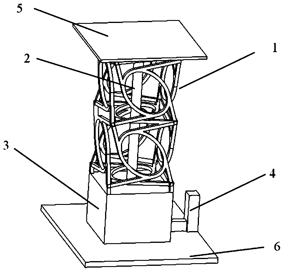
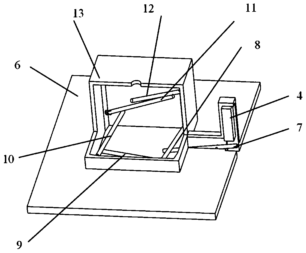
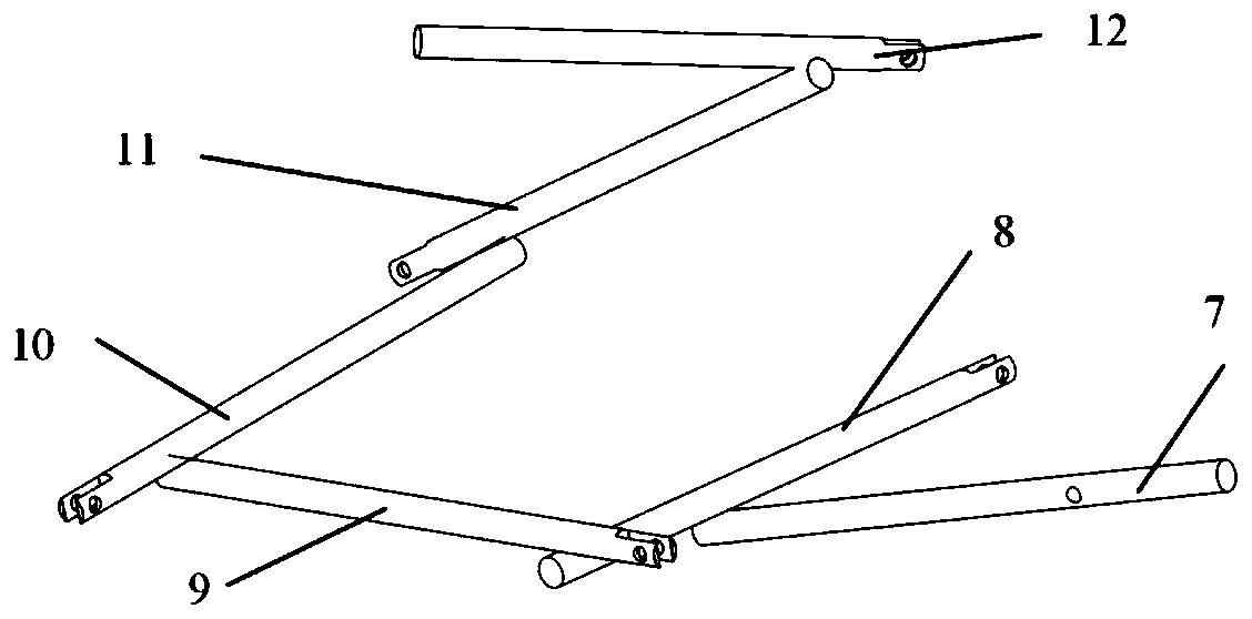
The invention provides a piezoelectric-driven three-dimensional micro-positioning platform comprising a rotating frame structure, an extension rod, a displacement amplifying device, a piezoelectric stack, a surface force-bearing plate, and a bottom plate. One end of the rotating frame structure is connected to the surface force-bearing plate and the other end is connected to the displacement amplifying device. The displacement amplifying device is installed on the bottom plate; and the piezoelectric stack is connected to the displacement amplifying device. The extension rod is arranged in therotating frame structure; and one end of the extension rod is connected to the displacement amplifying device and the other end is connected to the surface force-bearing plate. Under the piezoelectricstack driving, a force is applied to the rotating frame structure and thus the rotating frame structure is distorted by the force, thereby realizing the rotational movement of the positioning platform. According to the invention, with control of the output displacement of the piezoelectric stack, the precise control of the normal displacement of the positioning platform and the rotation angle ofthe horizontal plane is realized.

Description

technical field [0001] The invention belongs to the technical field of microscopic devices, and in particular relates to a piezoelectric-driven three-dimensional micro-positioning platform. Background technique [0002] Piezoelectric materials are widely used because of their stable output, anti-electromagnetic interference, and fast response. Among them, although the output displacement of the piezoelectric stack is small, it can ensure a stable displacement output when used with a displacement amplifier. [0003] At present, most of the positioning worktables mainly move linearly in the X-axis and Y-axis directions, with low precision and high production costs, and are mostly suitable for large strokes. In terms of micro-displacement platforms, the linear motion of the platform often cannot be matched with the rotary motion. The rotation of the platform requires additional force, which is not conducive to the structuralization and functional integration of the positioning...

Claims


Application Information

Patent Timeline
Patent Type & Authority Applications(China)
IPC IPC(8): G02B21/34G02B21/26
CPCG02B21/26G02B21/34
Inventor 黄俊邹磊李凯
Owner JIANGSU UNIV
Learn More