
Truss type extensible antenna reflector

An antenna reflector and frame technology, which is applied in the field of frame-type expandable antenna reflectors, can solve the problems that the light weight of the antenna cannot be satisfied and the space layout of a small size, the number of reflector truss rods increases, and the size of the folded increases, etc., to achieve The effect of reducing the weight of the reflector, reducing the number of trusses, and increasing the number of nodes

Active Publication Date: 2019-11-26
XIAN INSTITUE OF SPACE RADIO TECH
View PDF3 Cites 4 Cited by
  • Summary
  • Abstract
  • Description
  • Claims
  • Application Information

AI Technical Summary

Problems solved by technology

For this type of frame antenna structure, as the antenna diameter increases, the number of reflector truss rods will increase significantly in order to ensure the accuracy of the reflector profile, resulting in a significant increase in the weight of the antenna and an increase in the folded size, which cannot meet the requirements Requirements of the current task for the lightweight and tiny space layout of the antenna

Method used


Image

  • Truss type extensible antenna reflector
  • Truss type extensible antenna reflector
  • Truss type extensible antenna reflector

Examples


Embodiment Construction

[0031] The specific implementation of the present invention will be further described in detail below in conjunction with the drawings and specific embodiments.

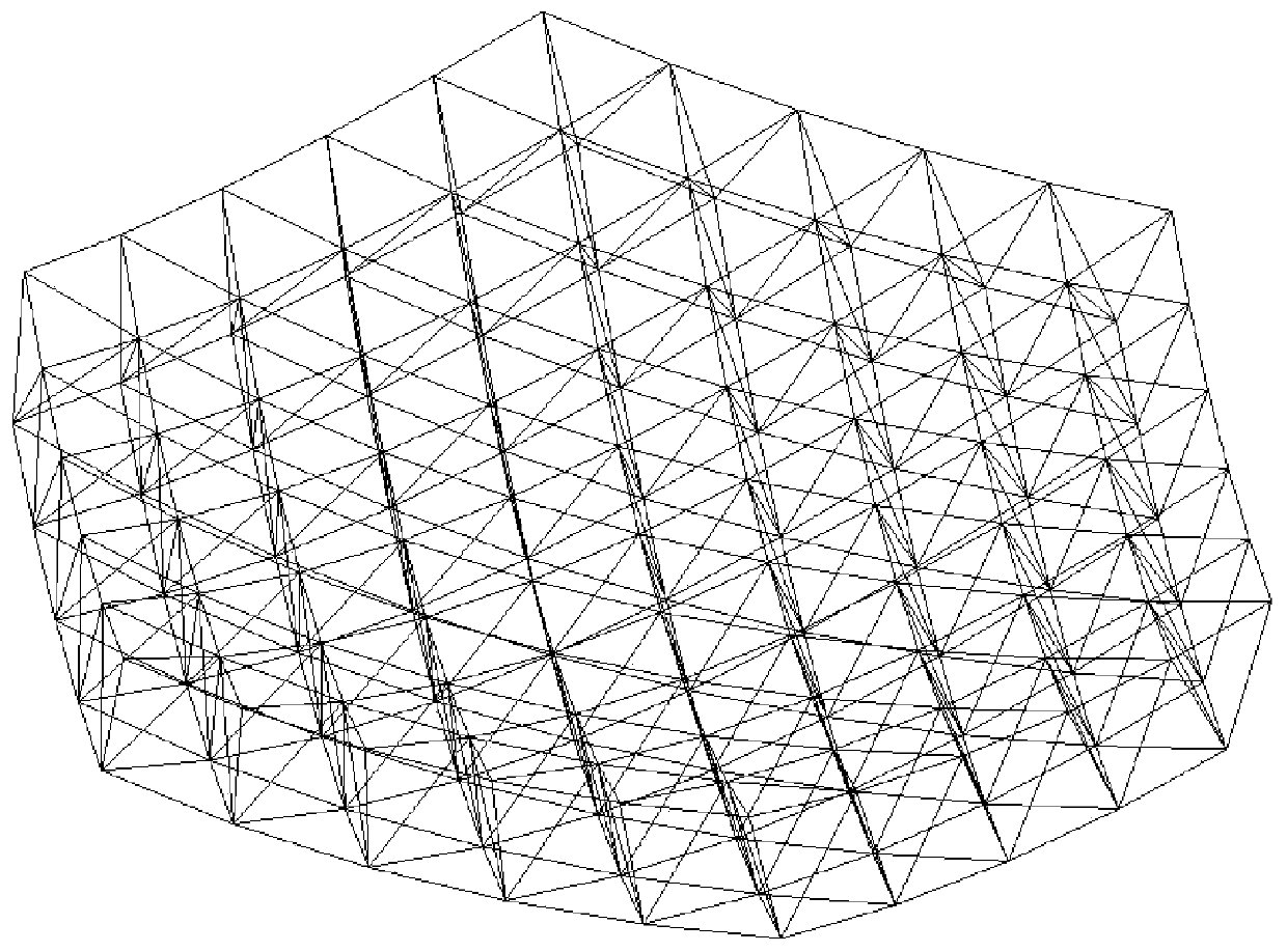
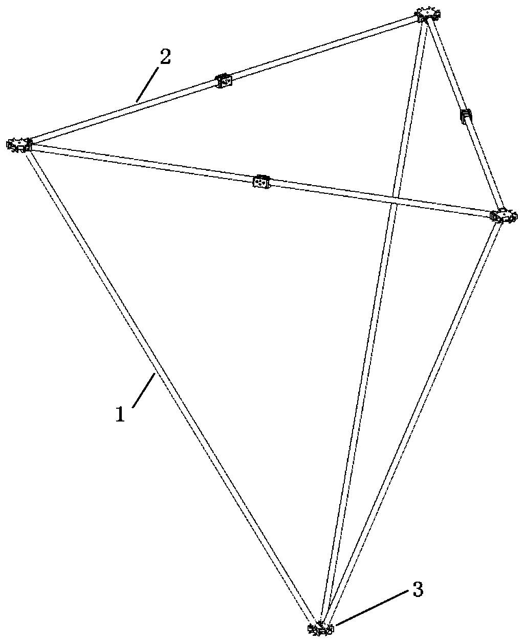
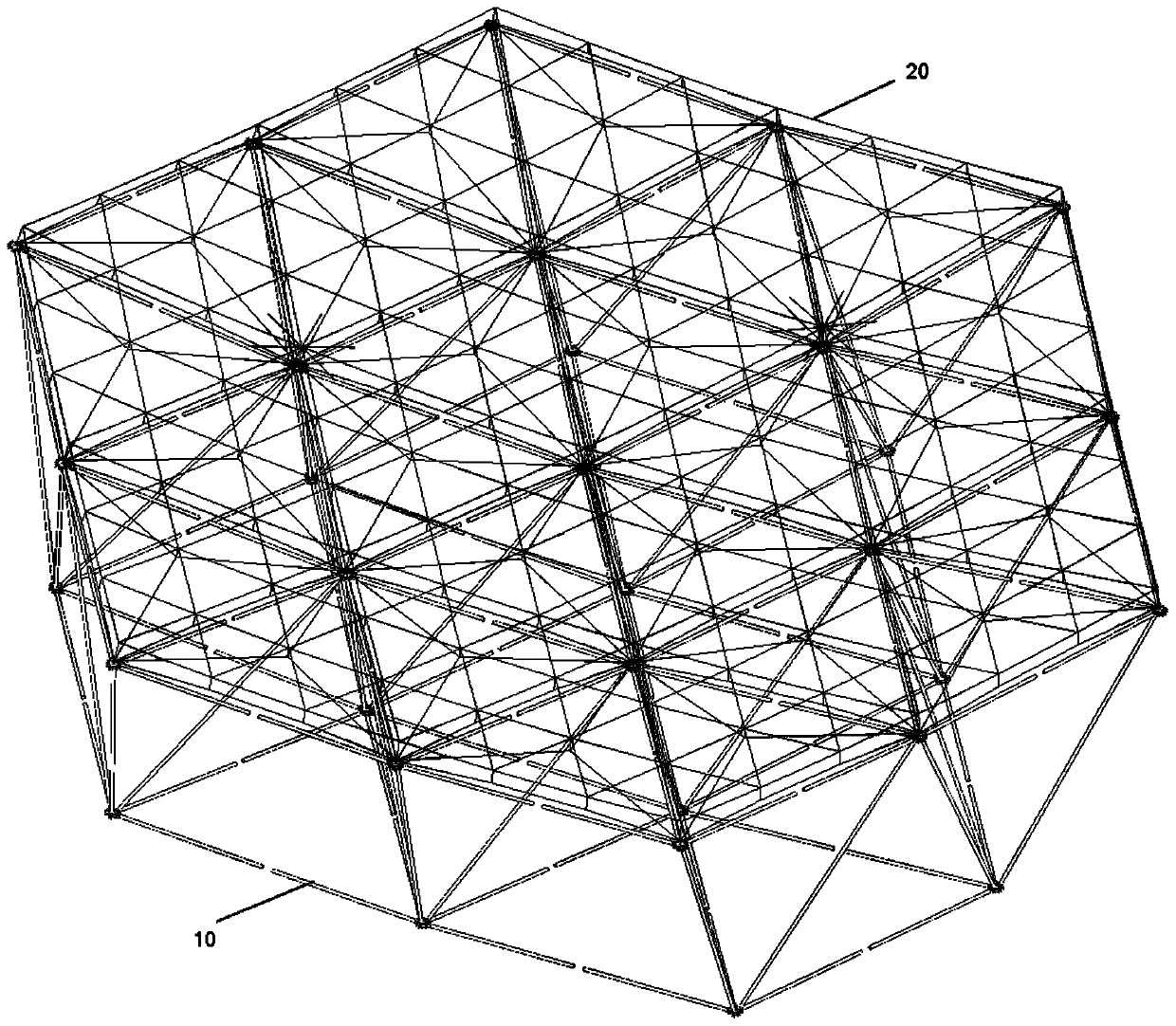
[0032] Such as figure 2 with 3 As shown, the embodiment of the present invention provides a framework-type deployable antenna reflector, including a truss 10, a metal mesh (not shown in the figure), and a cable mesh structure 20. The truss is formed by splicing truss elements, such as figure 2 As shown, the truss unit includes 3 web bars 1, 3 folding bars 2 and 4 faceplates 3. The 3 folding bars 2 enclose a triangle, and the web bars 1 correspond to the vertices of the triangle one by one. Fixed to form a tetrahedron structure, the faceplate 3 and the four vertices of the tetrahedron are fixed in one-to-one correspondence, such as Figure 4 As shown, the cable net structure includes an upper cable net 4, a lower cable net 5, a tension array 6 and a plurality of faceplate connecting columns 7, and the faceplate connectin...


PUM


Abstract

The embodiment of the present invention provides a truss type extensible antenna reflector, and belongs to the technical field of antennas. A cable-net structure of the reflector includes an upper layer of cable net, a lower layer of cable net, a tension array and multiple flower disc connecting columns; the flower disc connecting columns extend along a vertical direction; the upper layer of cablenet and the lower layer of cable net are fixedly stacked via the flower disc connecting columns on a net surface formed by folding rods; the upper layer of cable net is spliced by multiple first triangular lattice units; the lower layer of cable net is spliced by multiple second triangular lattice units; an exterior outline of each triangular lattice unit is matched with a triangle; at least onefirst node is provided at an edge of each first triangular lattice unit; a second node matched with the first node in one-to-one correspondence is provided at an edge of each second triangular latticeunit; and corresponding first nodes and second nodes are fixed by corresponding tension array ropes. The truss type extensible antenna reflector can increase the number of nodes without adding a truss unit, can reduce the weight of the reflector obviously, and improves the storage ratio.

Description

Technical field [0001] The present invention relates to the field of antenna technology, and in particular provides a framework-type deployable antenna reflector with light weight and high storage ratio. Background technique [0002] With the rapid development of aerospace science and technology and the increasing economic and military needs, major aerospace science and technology projects such as satellite communications, data relay, ground remote sensing, navigation, and electronic reconnaissance that are being implemented in aerospace engineering have increasingly increased requirements for spacecraft. At present, my country’s navigation and ground remote sensing are in the stage of load upgrade, subject to multiple satellites and small carrier envelope requirements. For antennas with a diameter of 3 to 8 meters, a collapsed envelope size of less than 1m×1m×1m is also proposed. The weight is 30~50Kg. At present, the various types of large-scale space expandable antennas availa...

Claims


Application Information

Patent Timeline
Patent Type & Authority Applications(China)
IPC IPC(8): H01Q1/08H01Q15/14H01Q15/16
CPCH01Q1/08H01Q15/14H01Q15/161
Inventor 黄志荣郑士昆马小飞朱佳龙赵将宋婷婷段玉柱徐小龙韩正鹰
Owner XIAN INSTITUE OF SPACE RADIO TECH
Learn More