
Crushing method, swirling collision crushing mechanism and multipolar crushing device

A technology of crushing mechanism and crushing device, applied in grain processing and other directions, can solve problems such as wear and tear of crushing equipment, and achieve the effect of avoiding wear and tear

Pending Publication Date: 2019-11-29
晏斯华
View PDF1 Cites 1 Cited by
  • Summary
  • Abstract
  • Description
  • Claims
  • Application Information

AI Technical Summary

Problems solved by technology

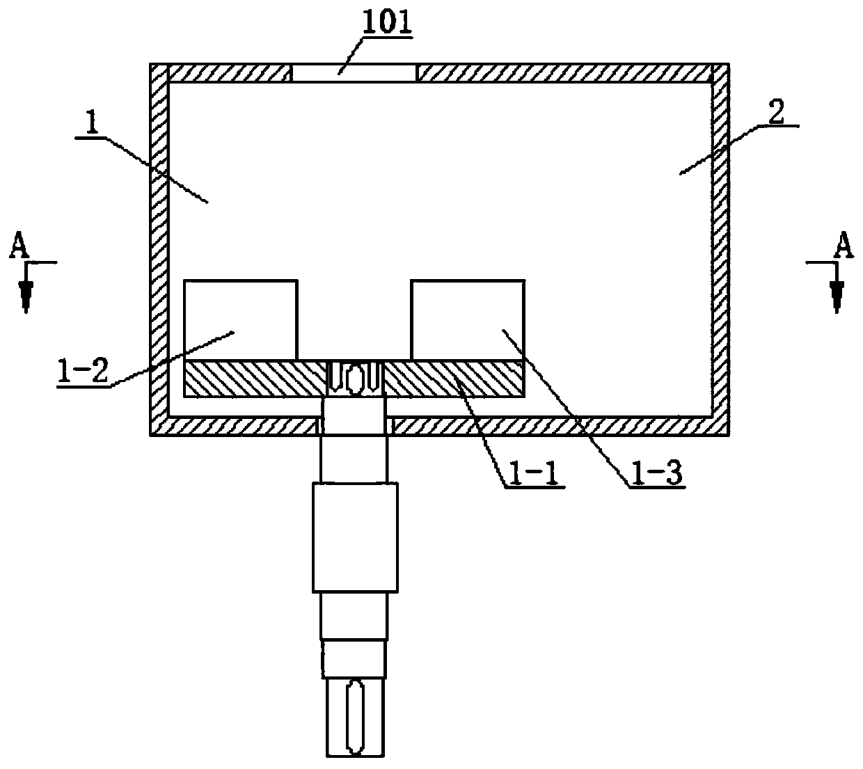
[0004] Based on the above-mentioned background problem, the present invention aims to provide a crushing method, through which the materials are thrown out tangentially under the action of high-speed rotation, and high-speed friction and collision are generated between the thrown materials, so as to realize the purpose of crushing materials and solve the current problem. There is a defect in the technology that causes wear and tear on the crushing equipment, and another object of the present invention is to provide a swirl-type collision crushing mechanism for implementing the above-mentioned crushing method, and a multi-pole crushing device including the above-mentioned swirl-type collision crushing mechanism

Method used


Image

  • Crushing method, swirling collision crushing mechanism and multipolar crushing device
  • Crushing method, swirling collision crushing mechanism and multipolar crushing device
  • Crushing method, swirling collision crushing mechanism and multipolar crushing device

Examples


Embodiment 1

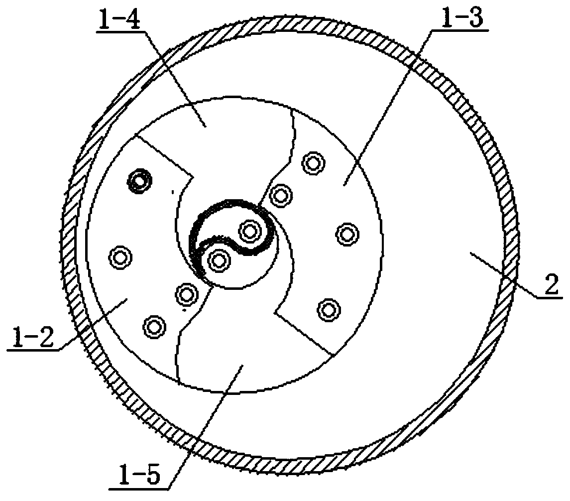
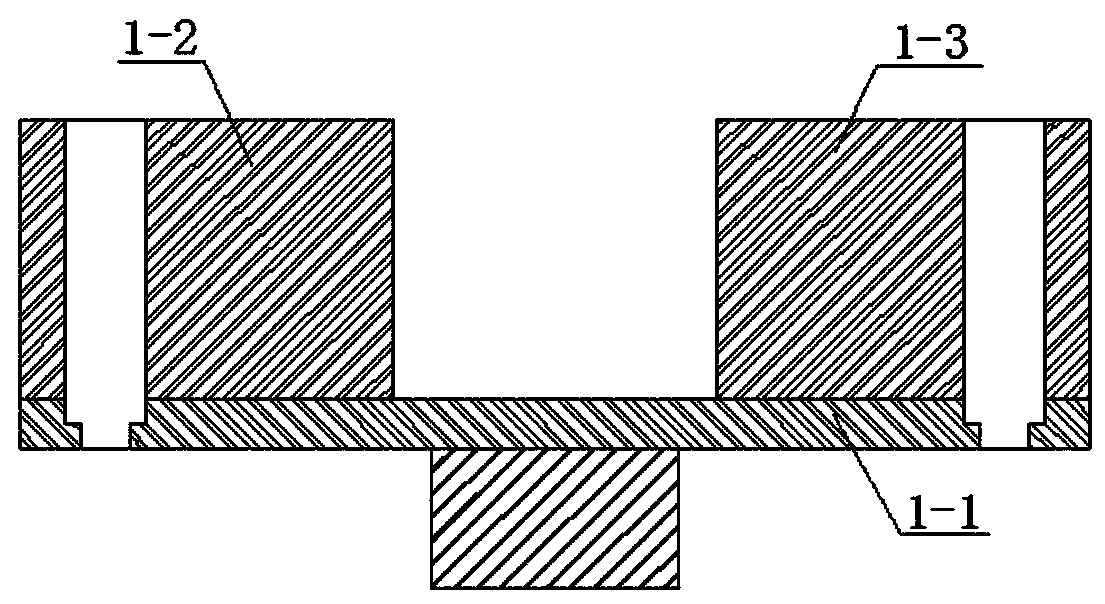
[0029] In order to solve the problems existing in the prior art, this embodiment provides a swirl type colliding crushing mechanism, such as Figure 1-3 As shown, it includes: a rotor assembly, which is accommodated in the material rejection chamber 1 provided with a feed inlet 101, and the rotation axis of the rotor assembly is arranged in a vertical direction, and is parallel to the material feeding direction so that the material is in the Under the action of the rotor assembly, it is thrown tangentially; it also includes a crushing chamber 2, which is horizontally connected with the material throwing chamber 1, so that the materials thrown out tangentially along the rotor assembly are collided and crushed in the crushing chamber 2. In this way, after the material is fed, it can be thrown out along the tangential direction under the high-speed rotation of the rotor assembly, and high-speed friction and collision will occur between the material particles thrown out along the t...

Embodiment 2

[0035] The present invention also provides a multi-pole crushing device, such as Figure 4 As shown, it includes a hopper 3 and a discharge chamber 4, and the swirl type colliding crushing mechanism of the embodiment 1 is communicated between the hopper 3 and the discharge chamber 4. Specifically, the hopper 3, the collision swirling crushing mechanism, and the discharge chamber 4 are distributed up and down in sequence.

[0036] In this embodiment, the discharge end of the hopper 3 is evenly provided with a plurality of material distribution ports 301 in a ring shape, and the material distribution ports 301 are connected with the material rejection chamber 1 in Embodiment 1, and each of the material removal ports Cavities 1 are provided with the collision swirl crushing mechanism. Specifically, such as Figure 5As shown, there are four throwing chambers 1, and the bottom end of the corresponding hopper 3 is provided with four distribution ports 301, that is, the distributio...


PUM


Abstract

The invention provides a crushing method, a swirling collision crushing mechanism and a multipolar crushing device, and belongs to the technical field of hard material crushing. According to the crushing method, materials are thrown out along a tangential direction under the action of high-speed rotation, and high-speed friction and collision is generated among the thrown materials, so that the purpose of material beating is realized. The swirling collision crushing mechanism adopting the crushing method comprises a rotor assembly arranged in a material throwing cavity with a material inlet; arotating axis line of the rotor assembly is perpendicular to the ground and is parallel to a material feeding direction, so that the materials are thrown out along the tangential direction under theaction of the rotor assembly; and the crushing mechanism further comprises a crushing cavity horizontally communicating with the material throwing cavity, so that the materials thrown out along the tangential direction of the rotor assembly are collided and crushed in the crushing cavity, and abrasion to crushing equipment is avoided. The invention further provides the multipolar crushing device comprising the swirling collision crushing mechanism.

Description

technical field [0001] The present invention belongs to the technical field of crushing hard materials, and specifically relates to a crushing method. In addition, the present invention also relates to a swirl-type collision crushing mechanism for implementing the above-mentioned crushing method, and a multi-pole crushing mechanism including the above-mentioned swirl-type collision crushing mechanism. device. Background technique [0002] At present, in the crushing process of superhard materials such as ores, the materials are generally crushed in the equipment through the extrusion of the tooth plate, or the direct impact of the rotation, or the impact of the hammer (plate). The contact processing process greatly increases the load and internal friction of the equipment, thereby reducing the service life of the equipment and increasing the maintenance cost. [0003] In order to solve the above technical problems, the prior art (CN109126987A) discloses a sand making machin...

Claims


Application Information

Patent Timeline
Patent Type & Authority Applications(China)
IPC IPC(8): B02C19/00B02C23/02B02C21/00B02C23/00
CPCB02C19/0025B02C19/0056B02C23/02B02C21/00B02C23/00
Inventor 晏斯华
Owner 晏斯华
Learn More