A robot intelligent refueling equipment

A robot and equipment technology, which is applied in the direction of manipulators, packaging, liquid distribution, transportation or transfer devices, etc., can solve the problems of not meeting the refueling requirements of large-flow refueling vehicles, irregular leakage of mechanical arms, and increasing the cost of gas stations. Achieve the effects of automatic operation, space saving, and flexible refueling methods

Active Publication Date: 2022-07-29
河南英高能源科技有限公司
View PDF8 Cites 0 Cited by
  • Summary
  • Abstract
  • Description
  • Claims
  • Application Information

AI Technical Summary

Problems solved by technology

At present, refueling mostly adopts the method of manual refueling. Although many gas stations have implemented self-service refueling, most gas stations are still equipped with operators to assist in refueling. Carry out refueling operations
When there are many refueling vehicles, it is difficult for fewer staff to take care of each refueling vehicle in an all-round way. If there are too many staff at the gas station, there will be a waste of human resources, and the efficiency of manual operation is relatively low. It is also low, and there will be work and operation errors, leading to safety accidents.
In addition to payment operations, fuel volume selection and other processes, the traditional manual refueling method can no longer meet the refueling needs of large-flow refueling vehicles
[0003] At present, there are many automatic refueling equipments on the market. These devices basically meet the needs of automatic refueling, but there are still some defects. These defects are mainly reflected in: First, the cost of the whole set of traditional automatic refueling equipment The fully automatic mechanical arm implements position change, and the automatic refueling equipment implemented by the mechanical arm takes up more space for the robotic arm itself. The attached refueling output device takes up more space overall, and the equipment occupies a large area. After the layout and installation, the impression is refueling The overall space utilization rate of the station will easily lead to excessive occupancy of the vehicle driving space, and the leaking part of the mechanical arm is irregular, which is likely to cause collisions and other phenomena; secondly, one traditional automatic refueling equipment can only meet the requirements of the working area. When refueling is carried out in the direction of incoming vehicles on one side, and automatic refueling needs to be implemented in the direction of incoming vehicles on the other side, it is often necessary to arrange two automatic refueling equipment, which causes a waste of resources and increases the cost of the gas station. The layout of two sets of equipment in the direction of two-way vehicles is implemented, which is the same as the layout of traditional manual refueling machines; again, once the traditional automatic refueling equipment is positioned at the refueling port, it will implement refueling operations at the refueling port, which affects the vehicle. Too close to the position is very strict. If the side vertical line of the side near the fuel dispenser is not parallel to the working surface of the fully automatic fuel dispenser after the vehicle stops, there will be obstruction or jamming of the fuel nozzle entering the fuel inlet. The reason for the problem is that the position of the car after parking is not moving, and the automatic refueling equipment needs to actively adjust to the position of the car. With the expansion of the overall adjustment space, when the distance between the vehicle and the tanker is too close, the movement of the mechanical arm will be hindered, resulting in fueling failure

Method used


Image

  • A robot intelligent refueling equipment
  • A robot intelligent refueling equipment
  • A robot intelligent refueling equipment

Examples


Embodiment Construction

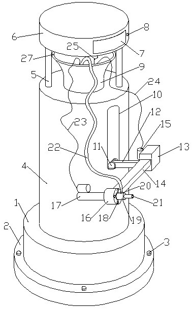
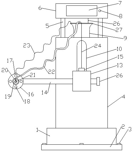
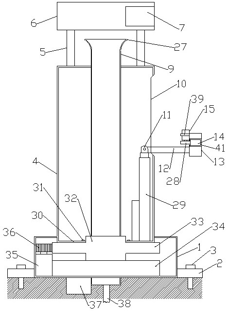
[0018] like figure 1 , 2 , 3 and 4, a robotic intelligent refueling device includes a central fixing sleeve 9, a bottom stable support 34 is fixedly installed on the outer side of the bottom of the central fixed sleeve 9, and the center above the bottom stable support 34 is fixed. A rotary bearing 32 is sleeved on the outer side of the fixed sleeve 9, a rotary toothed plate 33 is fixedly installed on the circumferential direction of the rotary bearing 32, and a bottom rotary motor 35 is fixedly mounted on one side of the bottom stable support 34, and the output end of the bottom rotary motor 35 is fixed It is fixedly connected with the bottom rotating gear 36, the rotating toothed plate 33 is meshed with the bottom rotating gear 36, the rotating drum 4 is fixedly installed on the top of the rotating toothed plate 33, and the bottom outer side of the rotating drum 4 is sheathed with a bottom bottom protective shell 1, at the bottom of the rotating drum 4. The top of the rotati...


PUM


Abstract

The invention relates to a robot intelligent refueling device. One end of a lateral lifting rod is located in a central fixed sleeve, an internal connecting seat is fixedly installed on the end of the lateral lifting rod located in the central fixed sleeve, and the bottom of the internal connecting seat is connected to the inner connecting seat. The output end of the lifting electric push rod is fixedly connected, the bottom of the lifting electric push rod is fixedly connected with the rotating tooth plate, the other end of the lateral lifting rod is located outside the central fixed sleeve, and the end of the lateral lifting rod outside the central fixed sleeve is located. A lateral support base is fixedly installed, a lateral movement slot is opened on the lateral support base, a lateral movement rod is movably installed in the lateral movement slot, and a lateral movement rod rotating gear is meshed and connected to the lateral movement rod tooth slot. The output end of the moving motor of the lateral movement rod installed on the lateral support base is connected; the tedious steps such as payment and oil quantity selection are reduced, and the refueling demand of large-flow refueling vehicles can be met.

Description

technical field [0001] The invention relates to a robot intelligent fueling device. Background technique [0002] With the development of science and technology and the improvement of people's living standards, more and more cars are used. In the process of using cars, it is inevitable to encounter the problem of refueling. At present, refueling is mostly done manually. Although many gas stations have implemented self-service refueling, most of them are still equipped with operators to assist in refueling. Carry out refueling operations. When there are many refueling vehicles, it is difficult for a small number of staff to take care of each refueling vehicle in an all-round way. With too many staff at the gas station, there will be a waste of human resources, and the efficiency of manual operation is relatively speaking. It is also lower, and there will be work and operational errors, resulting in safety accidents. In addition to payment operations, fuel selection and oth...

Claims


Application Information

Patent Timeline
Patent Type & Authority Patents(China)
IPC IPC(8): B25J11/00B67D7/04B67D7/06
CPCB25J11/00B67D7/04B67D7/06B67D7/0401B67D2007/0403B67D2007/0417
Inventor 林泽恩林茂松
Owner 河南英高能源科技有限公司
Why Eureka
Try Eureka