Vibration structure with adjustable excitation direction
A vibration excitation, vertical direction technology, used in roads, road repair, roads, etc., can solve the problem of not meeting the adjustment of vibration excitation direction and amplitude, and achieve high lubrication and heat dissipation efficiency, reliable and stable working process, fast and efficient. cooling effect
- Summary
- Abstract
- Description
- Claims
- Application Information
AI Technical Summary
Problems solved by technology
Method used
Image
Examples
Embodiment 1
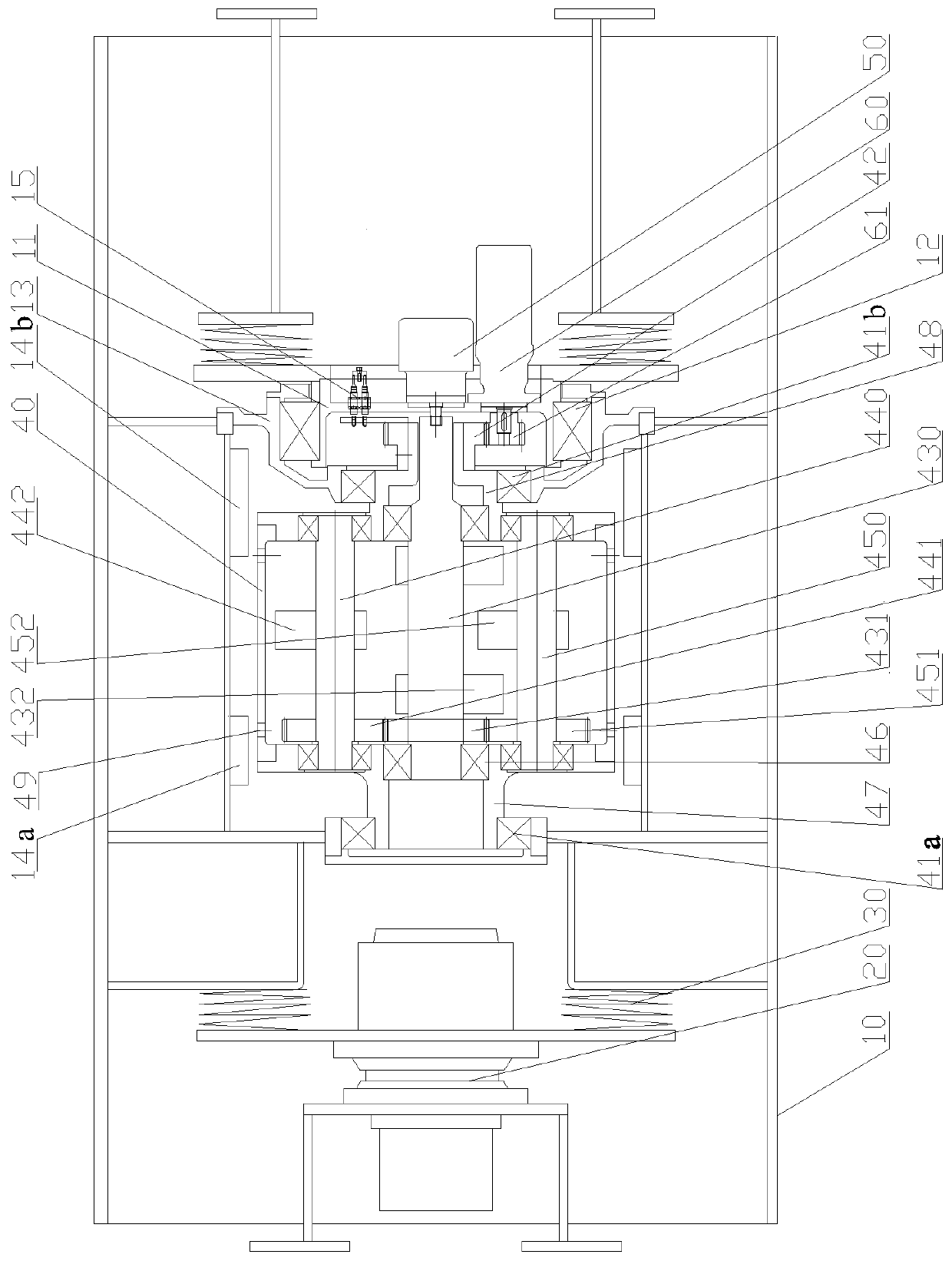
[0041] The specific structure of the present invention can refer to figure 1 As shown, it includes a suspended driving mechanism 20, a walking support bearing 12 that cooperates with the driving mechanism 20 to make the entire vibrating structure walk, a vibrating body 10, and an excitation cylinder 40 arranged in the vibrating main body 10, wherein the walking supporting bearing 12 Placed on the second bearing seat 13 , the vibration cylinder 40 is a vibration cylinder, and the vibration main body 10 is provided with a vibration motor 50 on one side of the vibration cylinder 40 . The cylinder cavity of the vibration cylinder 40 is provided with an eccentric shaft along the axial direction and an eccentric block group is provided on the eccentric shaft. The eccentric shafts include an active eccentric shaft 430 disposed on the centerline of the excitation cylinder 40 , and a first driven eccentric shaft 440 and a second driven eccentric shaft 450 symmetrically disposed on both...
Embodiment 2
[0044] On the basis of Embodiment 1, an angle adjustment part is added, so that the excitation direction of the vibration structure can be adjusted, and the structure after adding the angle adjustment part is as follows figure 1 shown.
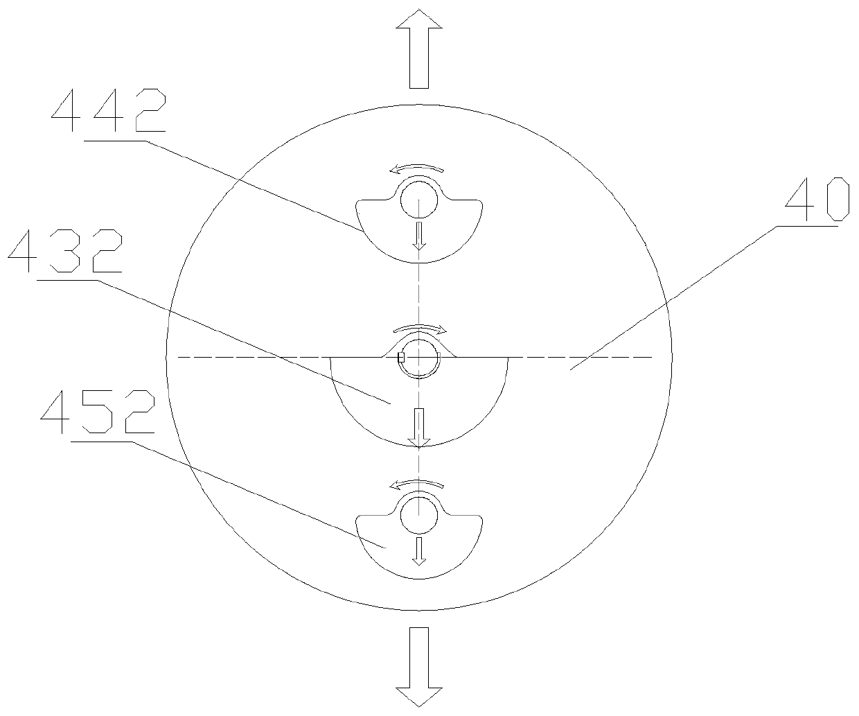
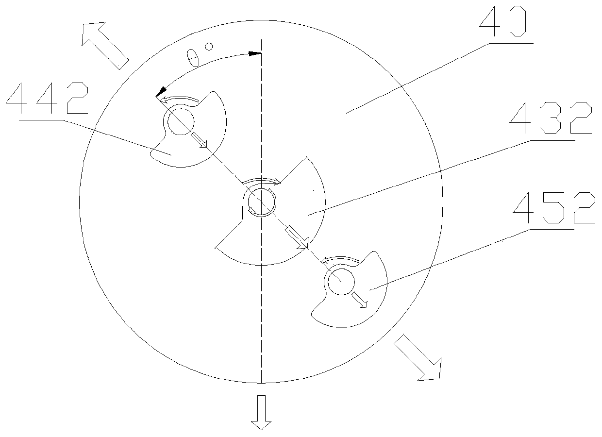
[0045] In order to ensure that the angle between the eccentric shaft and the vertical direction can be adjusted by adjusting the angle of the exciting cylinder 40, and then adjust the exciting force of the eccentric block group on the eccentric shaft and the angle of the vertical direction, to achieve the adjustment of the exciting force at amplitude in the vertical direction. Such as figure 1 As shown, the two ends of the vibration cylinder 40 pass through the insides of the left cylinder support bearing 41a and the right cylinder support bearing 41b, which can reduce the friction generated by rotation. The added angle adjustment part includes an angle adjustment motor 60, an angle detection sensor 15 and a control unit, an active adjustmen...
Embodiment 3
[0052] On the basis of Embodiments 1 and 2, in order to reduce the frictional force produced by each bearing and gear, the vibration structure is also provided with a first lubricating oil bucket 14a and a second lubricating oil bucket 14b, such as Figure 3a , 3b , 3c, the outer wall of the vibration cylinder 40 is provided with two groups of lubricating oil inlet holes 49 connecting the first lubricating oil bucket 14a and the cavity of the vibration cylinder 40, wherein one group of lubricating oil inlet holes 49 communicates with the first lubricating oil inlet hole 49. A lubricating oil bucket 14a and the cavity of the excitation cylinder 40 extend to the gear and bearing on the left side of the vibration cylinder 40, and another set of lubricating oil inlet holes 49 communicates with the second lubricating oil bucket 14b and the excitation cylinder. The cavity of the vibrating cylinder 40 extends to the bearing located on the right side inside the vibrating cylinder 40 ....
PUM
 Abstract
Description
Claims
Application Information
 - R&D
- Intellectual Property
- Life Sciences
- Materials
- Tech Scout
- Unparalleled Data Quality
- Higher Quality Content
- 60% Fewer Hallucinations
Browse by: Latest US Patents, China's latest patents, Technical Efficacy Thesaurus, Application Domain, Technology Topic, Popular Technical Reports.
© 2025 PatSnap. All rights reserved.Legal|Privacy policy|Modern Slavery Act Transparency Statement|Sitemap|About US| Contact US: help@patsnap.com


