
Heat supply system

A heat supply system and heat source technology, which is applied in the field of heating system and central heating system, can solve the problem of low waste heat utilization efficiency, and achieve the effects of improving energy use efficiency, low return water temperature, and reducing return water temperature

Pending Publication Date: 2019-11-29
SUZHOU BSE AIR CONDITIONER
View PDF1 Cites 1 Cited by
  • Summary
  • Abstract
  • Description
  • Claims
  • Application Information

AI Technical Summary

Problems solved by technology

[0004] The purpose of the present invention is to provide a heating system to solve the technical problem of low waste heat utilization efficiency in the prior art

Method used


Image

  • Heat supply system

Examples


Embodiment Construction

[0020] The technical solutions of the present invention will be clearly and completely described below in conjunction with the accompanying drawings. Apparently, the described embodiments are some of the embodiments of the present invention, but not all of them. Based on the embodiments of the present invention, all other embodiments obtained by persons of ordinary skill in the art without making creative efforts belong to the protection scope of the present invention.

[0021] In the description of the present invention, it should be noted that the terms "center", "upper", "lower", "left", "right", "vertical", "horizontal", "inner", "outer" etc. The indicated orientation or positional relationship is based on the orientation or positional relationship shown in the drawings, and is only for the convenience of describing the present invention and simplifying the description, rather than indicating or implying that the referred device or element must have a specific orientation, ...


PUM


Abstract

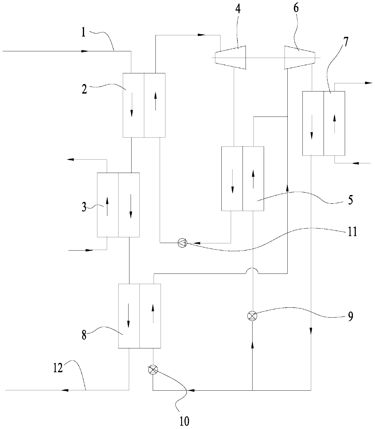
The invention provides a heat supply system which comprises a heat supply assembly, an expansion work recovery assembly and a refrigerating assembly. A heat source passes through a steam generator first to transfer part of heat to a first working medium, and then the heat source is transferred to a first heat supply heat exchanger and supplies heat to a user; the first working medium absorbing heat becomes overheated steam, the overheated steam becomes low temperature steam after being acted by an expansion machine, the low temperature steam transfers parts of heat to a second working medium through a condenser, and the first working medium forms reflux; the expansion machine drives a compressor to act and compresses the second working medium of gas to high temperature and high pressure gas, heat is transferred to a second heat supply heat exchanger and is supplied to the user, and the second working medium returns to the condenser to form circulation. The expansion machine is driven by the high temperature heat source to provide power to the compressor, so that the return water temperature is reduced, the heat supply capacity of an existing pipe network is improved and the energyuse efficiency of the heat supply system is improved on the premise of not increasing extra acting electric power.

Description

technical field [0001] The invention relates to the technical field of central heating systems, in particular to a heating system. Background technique [0002] With the continuous development of the city scale and the gradual improvement of people's living standards, the urban heating area continues to increase, and the existing central heating pipe network can no longer meet the growing heating demand. Therefore, it is necessary to re-plan the existing heating pipes. Network, but the transformation of the existing heating pipe network needs to consume huge funds. The primary network design of the existing urban central heating supply and return water temperature is generally 130°C and 70°C, and the temperature difference is 60°C. If the return water temperature is reduced to 20°C, the heating capacity can be nearly doubled. [0003] The patent application with the publication number CN100507375C discloses a central heating system with a large temperature difference, which...

Claims


Application Information

Patent Timeline
Patent Type & Authority Applications(China)
IPC IPC(8): F24D3/18
CPCF24D3/18F24D2200/13
Inventor 查晓冬魏辉
Owner SUZHOU BSE AIR CONDITIONER
Learn More